|
ac9wzw00002309
TIMING CHAIN REMOVAL/INSTALLATION [MZI-3.7]
id0110c5801000
1. Drain the engine oil. (See ENGINE OIL REPLACEMENT [MZI-3.7].)
2. Remove the engine and transaxle component. (See ENGINE REMOVAL/INSTALLATION [MZI-3.7].)
3. Secure the engine and transaxle component using a hoist and the SST.
ac9wzw00002309
|
4. Remove the dynamic chamber and throttle body as a single unit. (See INTAKE-AIR SYSTEM REMOVAL/INSTALLATION [MZI-3.7].)
5. Remove the ignition coils. (See IGNITION COIL REMOVAL/INSTALLATION [MZI-3.7].)
6. Remove the dipstick.
7. Remove the power steering oil pump drive belt. (See DRIVE BELT REMOVAL/INSTALLATION [MZI-3.7].)
8. Remove the power steering oil pump. (See POWER STEERING OIL PUMP REMOVAL/INSTALLATION [L.H.D.].)(See POWER STEERING OIL PUMP REMOVAL/INSTALLATION [R.H.D.].)
9. Remove in the order indicated in the table.
10. Install in the reverse order of removal.
11. Start the engine and:
12. Perform a road test.
ac9wzw00002310
|
|
1
|
Drive belt auto tensioner
|
|
2
|
Crankshaft pulley lock bolt
|
|
3
|
Crankshaft pulley
|
|
4
|
Front oil seal
(See Front Oil Seal Removal Note.)
|
|
5
|
Cylinder head cover (LH)
|
|
6
|
Cylinder head cover (RH)
|
|
7
|
Cylinder head cover oil seal (LH)
|
|
8
|
Cylinder head cover oil seal (RH)
|
|
9
|
No.3 engine mount bracket
|
|
10
|
Engine front cover
|
|
11
|
OCV component (LH)
(See OCV Component Removal Note.)
|
|
12
|
OCV component (RH)
(See OCV Component Removal Note.)
|
|
13
|
Chain tensioner
|
|
14
|
Timing chain component
|
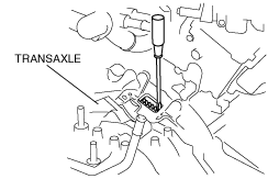
Crankshaft Pulley Lock Bolt Removal Note
1. Remove the starter. (See STARTER REMOVAL/INSTALLATION [MZI-3.7].)
2. Set a flathead screwdriver to the drive plate in the position indicated in the figure to lock the crankshaft rotation.
ac9wzw00002311
|
3. Remove the crankshaft pulley lock bolt and washer.
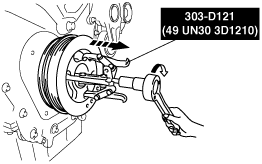
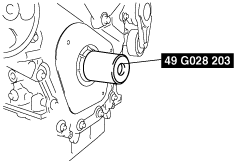
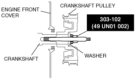
Crankshaft Pulley Removal Note
1. Remove the washer from the crankshaft pulley lock bolt, install a suitable spacer (thickness: approx. 14 mm {0.55 in}, diameter: approx. 30 mm {1.18 in}), (similar to front shock absorber lower nut) to the crankshaft pulley lock bolt, and install the crankshaft pulley lock bolt to the crankshaft.
ac9wzw00002312
|
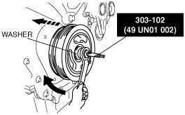
2. Remove the crankshaft pulley using the SST.
ac9wzw00002313
|
3. Remove the crankshaft pulley lock bolt and spacer.
Front Oil Seal Removal Note
1. Remove the front oil seal using a flathead screwdriver as shown.
ac9wzw00002314
|
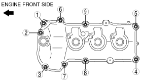
Cylinder Head Cover Removal Note
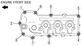
1. Remove the cylinder head cover bolts in the order shown.
RH
ac9uuw00003745
|
LH
ac9wzw00002317
|
Cylinder Head Cover Oil Seal Removal Note
1. Tap the OCV attachment hole seals and spark plug tube attachment hole seals using the SSTs and hammer.
ac9wzw00002318
|
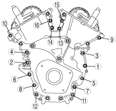
Engine Front Cover and No.3 Engine Mount Bracket Removal Note
1. Loosen the engine front cover and No.3 engine mount bracket installation bolts in the order shown in the figure.
ac9wzw00002319
|
2. Install 4 of the engine front cover bolts (finger tightened) into the 4 threaded holes in the engine front cover.
ac9wzw00002320
|
OCV Component Removal Note
1. Loosen the OCV component installation bolts in the order shown in the figure.
RH
ac9wzw00002321
|
LH
ac9wzw00002322
|
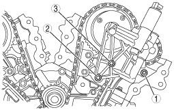
Timing Chain Component Removal Note
1. Turn the crankshaft clockwise so that the crankshaft keyway is in the 11 o’clock position. (This will position the No.1 cylinder at TDC.)
ac9wzw00002323
|
2. Mark the timing chain at the position of each timing sprocket timing mark.
azzjjw00000157
|
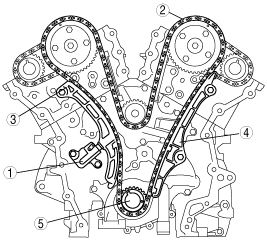
3. Remove the timing chain in the following order.
ac9wzw00002325
|
Timing Chain Component Installation Note
1. Verify that the crankshaft keyway is at 11 o’clock position.
ac9wzw00002326
|
2. If the timing marks on the timing chain are not evident, place timing marks on the timing chain using an indelible ink marker.
ac9wzw00003212
|
3. Place alignment marks on the timing chain corresponding to each of the alignment marks on the timing sprocket.
ac9wzw00002900
|
4. Using a thin screwdriver, hold the chain tensioner ratchet lock mechanism away from the ratchet stem.
5. Slowly compress the plunger.
6. Hold the plunger using a approx. 1.5 mm {0.059 in} wire.
ac9wzw00002901
|
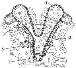
7. Install the timing chain in the following order.
ac9wzw00002332
|
8. Remove the retaining wire.
ac9wzw00002902
|
OCV Component Installation Note
1. Tighten the OCV component installation bolts in the order shown in the figure.
RH
ac9wzw00002334
|
LH
ac9wzw00002335
|
Engine Front Cover and No.3 Engine Mount Bracket Installation Note
1. Apply the silicon sealant (Loctite 5900) to the engine front cover shown in the figure.
ac9wzw00001418
|
2. Install the engine front cover and No.3 engine mount bracket.
ac9wzw00002336
|
Tightening torque
|
Step |
Installation position |
Tightening torque |
|---|---|---|
|
1
|
1—6
|
10 N·m {102 kgf·cm, 89 in·lbf}
|
|
2
|
7—9
|
15 N·m {1.5 kgf·m, 11 ft·lbf}
|
|
3
|
1—6
|
20—28 N·m {2.1—2.8 kgf·m, 15—20 ft·lbf}
|
|
4
|
7—9
|
70—80 N·m {7.2—8.1 kgf·m, 52—59 ft·lbf}
|
ac9wzw00002337
|
Cylinder Head Cover Oil Seal Installation Note
1. Push the OCV attachment hole seals and spark plug tube attachment hole seals slightly in by hand.
2. Tap the OCV attachment hole seals and spark plug tube attachment hole seals using the SST and hammer.
ac9wzw00002338
|
Cylinder Head Cover Installation Note
1. Apply silicone sealant (Loctite 5900) to the mating faces as shown.
RH
ac9wzw00002339
|
LH
ac9wzw00002340
|
2. Install the cylinder head cover with a new gasket.
3. Tighten the bolts in the order as shown.
RH
ac9wzw00002343
|
LH
ac9wzw00002344
|
Front Oil Seal Installation Note
1. Push the front oil seal slightly in by hand.
2. Tap the front oil seal in evenly using the SST and a hammer.
ac9wzw00002345
|
Crankshaft Pulley Installation Note
1. Install the crankshaft pulley, washer, and SST to the crankshaft.
ac9wzw00002346
|
2. Tighten the SST nut and install the crankshaft pulley.
ac9wzw00002347
|
Crankshaft Pulley Lock Bolt Installation Note
1. Set a flathead screwdriver to the drive plate in the position indicated in the figure to lock the crankshaft rotation.
ac9wzw00002348
|
2. Tighten the new crankshaft pulley lock bolt in four steps.
3. Install the starter. (See STARTER REMOVAL/INSTALLATION [MZI-3.7].)