 |
ac9wzw00002875
INTAKE-AIR SYSTEM REMOVAL/INSTALLATION [MZI-3.7]
id0113c3801900
1. Complete the “BEFORE SERVICE PRECAUTION”. (See BEFORE SERVICE PRECAUTION [MZI-3.7].)
2. Remove the battery. (See BATTERY REMOVAL/INSTALLATION [MZI-3.7].)
3. Remove the engine cover. (See ENGINE COVER REMOVAL/INSTALLATION [MZI-3.7].)
4. Disconnect the wiring harness.
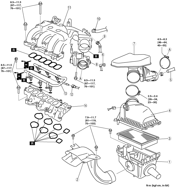
5. Remove in the order indicated in the table.
6. Install in the reverse order of removal.
7. Complete the “AFTER SERVICE PRECAUTION”. (See AFTER SERVICE PRECAUTION [MZI-3.7].)
ac9wzw00002875
|
|
1
|
Air cleaner case
|
|
2
|
Fresh-air duct
|
|
3
|
Air cleaner element
|
|
4
|
Air cleaner cover
|
|
5
|
Vacuum hose (to master back)
|
|
6
|
Ventilation hose
|
|
7
|
Resonance chamber
|
|
8
|
Throttle body
|
|
9
|
Vacuum hose (to purge solenoid valve)
|
|
10
|
Vacuum hose (to master back)
|
|
11
|
Dynamic chamber
|
|
12
|
Fuel hose
|
|
13
|
Fuel distributor
|
|
14
|
Intake manifold
(See Intake Manifold Removal Note.)
|
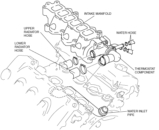
Intake Manifold Removal Note
1. Drain the engine coolant. (See ENGINE COOLANT REPLACEMENT [MZI-3.7].)
2. Disconnect the following parts:
ac9wzw00002134
|
3. Remove the intake manifold and thermostat component as a single unit.
4. Remove the thermostat component from the intake manifold.
ac9wzw00001327
|
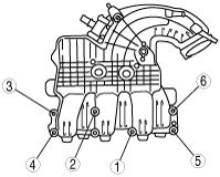
Intake Manifold Installation Note
1. Tighten the intake manifold installation bolts in the order shown.
ac9wzw00002135
|
Dynamic Chamber Installation Note
1. Tighten the dynamic chamber installation bolts in the order shown.
ac9wzw00002136
|