SHIFT SOLENOID A REMOVAL/INSTALLATION [AY6A-EL, AY6AX-EL]
id0517k3299600
-
Warning
-
• A hot transaxle and ATF can cause severe burns. Turn off the engine and wait until then are cool.
• Using compressed air can cause dirt and other particles to fly out, causing injury to the eyes. Wear protective eyeglasses whenever using compressed air.
-
Caution
-
• Water or foreign objects entering the connector can cause a poor connection or corrosion. Be sure not to drop water or foreign objects on the connector when disconnecting it.
1. Disconnect the negative battery cable.
2. Remove the fresh-air duct and air cleaner component as a single unit. (See INTAKE-AIR SYSTEM REMOVAL/INSTALLATION [MZI-3.7].)
3. Remove the air cleaner bracket. (See INTAKE-AIR SYSTEM REMOVAL/INSTALLATION [MZI-3.7].)
4. Clean the transaxle exterior throughout with a steam cleaner or cleaning solvents.
5. Drain the ATF. (See AUTOMATIC TRANSAXLE FLUID (ATF) REPLACEMENT [AY6A-EL, AY6AX-EL].)
6. Disconnect the oil hose from the oil cooler. (See OIL COOLER REMOVAL/INSTALLATION [AY6A-EL, AY6AX-EL].)
7. Disconnect the oil cooler from the transaxle with the water hose connected, and set it out of the way. (See OIL COOLER REMOVAL/INSTALLATION [AY6A-EL, AY6AX-EL].)
8. Disconnect the oil hose from the oil pipe component (transaxle side). (See OIL COOLER REMOVAL/INSTALLATION [AY6A-EL, AY6AX-EL].)
9. Remove the oil pipe component (transaxle side). (See OIL COOLER REMOVAL/INSTALLATION [AY6A-EL, AY6AX-EL].)
10. Remove the control valve body cover. (See CONTROL VALVE BODY COVER REPLACEMENT [AY6A-EL, AY6AX-EL].)
-
Note
-
• Disconnect the solenoid connector according to the following procedure:
-
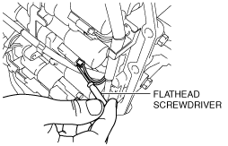
i. Insert a precision flathead screwdriver from the backside into the connector as shown in the figure.
-
Caution
-
• Do not damage the solenoid valves and connectors with the flathead screwdriver.
ii. Pry the flathead screwdriver in the direction of the arrow and disconnect the connector.
-
Caution
-
• When disconnecting connectors, grasp the connectors, not the wiring harnesses. Otherwise, the wiring harnesses may be pulled out of the connector causing poor contact.
11. Disconnect the shift solenoid A connector.
12. Remove the shift solenoid A from the control valve body.
13. Install the shift solenoid A to the control valve body.
-
Caution
-
• Do not damage the shift solenoid A.
-
Tightening torque
-
6.0—8.0 N·m {62—81 kgf·cm, 54—70 in·lbf}
14. Connect the shift solenoid A connector.
15. Install the new control valve body cover. (See CONTROL VALVE BODY COVER REPLACEMENT [AY6A-EL, AY6AX-EL].)
16. Install the oil pipe component (transaxle side). (See OIL COOLER REMOVAL/INSTALLATION [AY6A-EL, AY6AX-EL].)
17. Connect the oil hose to the oil pipe component (transaxle side). (See OIL COOLER REMOVAL/INSTALLATION [AY6A-EL, AY6AX-EL].)
18. Install the oil cooler to the transaxle. (See OIL COOLER REMOVAL/INSTALLATION [AY6A-EL, AY6AX-EL].)
19. Connect the oil hose to the oil cooler. (See OIL COOLER REMOVAL/INSTALLATION [AY6A-EL, AY6AX-EL].)
20. Install the air cleaner bracket. (See INTAKE-AIR SYSTEM REMOVAL/INSTALLATION [MZI-3.7].)
21. Add ATF. (See AUTOMATIC TRANSAXLE FLUID (ATF) LEVEL ADJUSTMENT [AY6A-EL, AY6AX-EL].)
22. Install the fresh-air duct and air cleaner component as a single unit. (See INTAKE-AIR SYSTEM REMOVAL/INSTALLATION [MZI-3.7].)
23. Connect the negative battery cable.
24. Adjust the ATF level. (See AUTOMATIC TRANSAXLE FLUID (ATF) LEVEL ADJUSTMENT [AY6A-EL, AY6AX-EL].)
25. Perform the “MECHANICAL SYSTEM TEST”. (See MECHANICAL SYSTEM TEST [AY6A-EL, AY6AX-EL].)
26. Perform the “ROAD TEST”. (See ROAD TEST [AY6A-EL, AY6AX-EL].)
 am6xuw00004105
 am6xuw00004106
