SERVICE CAUTIONS
id000000700900
Risk of injury or damage
-
Warning
-
<<High voltage>>
• When working on a high voltage system, mistaken operation could cause a serious accident such as electrical shock and result in serious injury or, in the worst case, death. Additionally, when handling an electric vehicle, work must be performed by persons who have acquired qualifications specified by laws and regulations. When servicing high voltage parts, refer to the [HIGH VOLTAGE SERVICE CAUTIONS] and perform the servicing according to the correct servicing procedure. (See
HIGH VOLTAGE SERVICE CAUTIONS.)
• Because electric vehicles are silent even when the EV system is operating, injury could result from getting caught in a cooling fan that operates unexpectedly. Verify that the READY indicator in the instrument cluster and the power switch indicator light are turned off and perform servicing while the system is stopped. Additionally, remove the remote transmitter from the vehicle so that other workers do not easily switch the main power ON (READY on).
• If the main power is switched ON (READY on) and the charge connector is connected to the vehicle, high voltage may be supplied to the vehicle. If servicing is performed under this condition, it could cause electrical shock and result in serious injury or, in the worst case, death. (See
HIGH VOLTAGE SERVICE CAUTIONS.)
-
Warning
-
• The cooling fan may suddenly start operating regardless of the main power switch position. Keep hands and tools away from the cooling fan even if the cooling fan is not operating to prevent injury, or damage to the cooling fan. When servicing the cooling fan or parts near the cooling fan,ensure the following.
-
― Do not perform normal charging or quick charging
― Do not select high voltage battery cooling on center display after EV system stops
― Do not open/close doors frequently with main power switched OFF
― Switch to connected vehicle maintenance mode (MyMazda App connected vehicle)
― Cancel climate control timer
― Operate center display and turn off battery heater operation
• Keep hands and tools away from the cooling fan even if the cooling fan is not operating to prevent an accident or damage.
• When servicing the cooling fan or parts near the cooling fan, disconnect the negative lead acid battery terminal and main relay No.1, and verify that the indicators in the instrument cluster are all turned off.
-
Warning
-
<<High voltage>>
• The high voltage battery uses a lithium-ion battery. The high voltage battery electrolytes are flammable. If the electrolyte leaks, immediately move sparks and flames away. In addition, ventilate well, wear solvent-resistant protective gear and wipe off any leaked electrolyte with a clean rag.
• Leaked electrolyte and its vapors can react with moisture in the air and produce acidic substances that are irritating to the skin and eyes. Therefore, if the electrolyte comes into contact with your skin or eyes, wash the area thoroughly with a large amount of running water and consult a doctor immediately.
-
Caution
-
<<High voltage>>
• Dispose of the cloth used to wipe off high voltage battery electrolyte in accordance with regulations.
-
Note
-
• The high voltage battery electrolyte is colorless and transparent and has an aromatic odor.
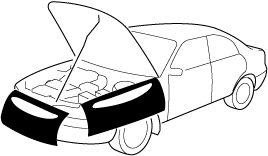
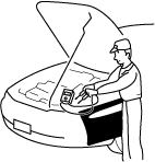
Vehicle Protection
• Before servicing, install the fender cover, seat cover, steering cover, and floor covering.
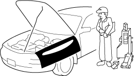
Tool and Measuring Equipment Preparation
• Before servicing, prepare all necessary tools, measuring equipment, and SSTs listed in the servicing procedure.
Special Service Tools
• If there is an SST instruction in the work procedure, use the applicable SST.
Malfunction diagnosis system
• Use the Mazda modular diagnostic system (M-MDS) for malfunction diagnosis.
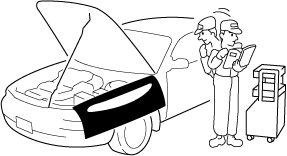
Connection to malfunction diagnosis system
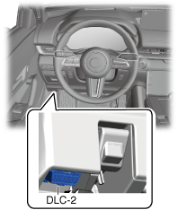
-
• With the main power switched OFF, connect the malfunction diagnosis system to the DLC-2 connector shown in the figure.
Negative lead-acid battery terminal disconnection/connection
-
Warning
-
-
Note
-
• Be careful not to close the liftgate with the negative lead-acid battery terminal disconnected. If the negative lead-acid battery terminal is disconnected, the liftgate cannot be opened because power is not supplied to the liftgate opener system.
Also, if the lead-acid battery is discharged, the liftgate cannot be opened because power is not supplied to the liftgate opener system.
• If the liftgate has been closed, perform manual release of the liftgate latch to open the liftgate.
• When disconnecting the negative lead-acid battery terminal, wrap the liftgate lock striker with a clean rag to prevent the liftgate from closing.
Procedures required after disconnecting/connecting negative lead-acid battery terminal
|
System name
|
Conditions after disconnecting negative lead-acid battery terminal
|
Required procedure
|
Reference
|
|
Before disconnecting the negative lead-acid battery terminal
|
After connecting the negative lead-acid battery terminal
|
|
Sunroof system
|
Initial settings are reset, and operations are disabled.
|
—
|
Perform the initial settings of the sunroof system.
|
|
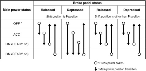
Switching and starting the power supply with the power switch
• The main power is switched by operating the power switch as shown in the figure below.
* :To switch the main power from ON (READY on) to ACC or OFF, the vehicle speed must be 5 km/h {3 mph} or less.
Removal of Parts
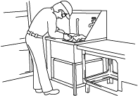
• After determining the damage or malfunction, perform the malfunction diagnosis and perform safe and efficient servicing. Before removing the part, verify the assembled condition, and inspect for deformities and damage. After removing the part, cover it with a clean cloth and packing tape so that foreign matter or small parts do not penetrate it. Place the removed part on a clean workbench, otherwise it may become damaged or lost if it is placed on the floor.
Control module configuration
-
Caution
-
• If the configuration procedure is not completed correctly after replacing a control module which requires configuration, the system will not operate normally. Therefore, perform the configuration in accordance with the replacement procedure in the workshop manual.
• If a control module is replaced, depending on the control module, it may be necessary to write the vehicle specification data to the new control module using the M-MDS. This writing procedure is called configuration.
Disassembly
• When disassembling a complex part, place a marking or alignment mark where performance or external appearance will not be affected so that reassembly can be performed easily and efficiently.
Inspection During Removal and Disassembly
• Visually inspect the assembled condition for deformation and damage each time a part is removed.
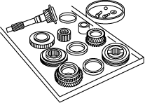
Arrangement of Parts
• Arrange the removed/disassembled parts in an orderly fashion so as not to mix them up and not let them become dirty. In addition, separate the parts to be replaced from the parts to be reused.
Cleaning of Parts
• Thoroughly clean and wash the parts to be reused.
Assembly
1. Follow the procedures correctly and observe the standard values (tightening torque, adjustment value) when assembling.
2. When the following parts are removed, replace them with new ones.
|
Oil seal
|
Cotter pin
|
|
Gasket
|
Locknut
|
|
O-ring
|
Roll pin
|
|
Lock washer
|
—
|
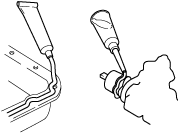
3. Depending on the gasket location, apply sealant before installing the part. Install the part before the sealant hardens.
4. Apply oil to the moving components of each part before assembling the part.
5. Apply the specified oil or grease to the specified locations (oil seals) before assembling the part.
Adjustment
• Adjust to the standard using measuring equipment.
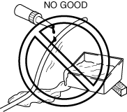
Rubber Parts and Tubing
• Do not allow oil to get on the rubber parts or tubing.
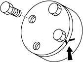
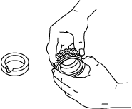
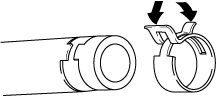
Installing/Removing the Hose Clamp
1. When reusing each hose, install the hose clamp onto the original hose clamp imprint.
2. After installation, apply force to the hose clamp in the direction of the arrows to engage the hose clamp securely.
-
Note
-
• Follow the description in each section because the clamps which are used with the fuel system differ from the above.
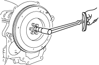
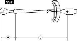
Torque Formulas
• When using a torque wrench together with an SST, use the following formulas to calculate the specified torque value due to the extra length that the SST adds to the torque wrench.
Formula
-
A: The length of the SST exceeding the effective length of the torque wrench.
L: Torque wrench length
N·m ×[L/(L+A)]
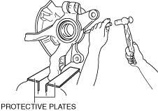
Vise
• When using a vise, insert protective plates into the opening of the vise to prevent damage to the parts.
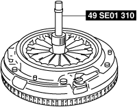
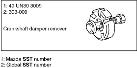
SST
• Some Ford manufactured SSTs are used on the SSTs necessary for servicing.
Be advised that these SSTs are marked with Ford SST numbers.
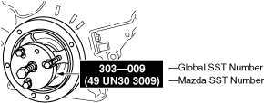
Be advised that the SST numbers of Mazda and Ford are written jointly so that the Ford SST number collates with Mazda as shown in the following description examples in this manual.
Example of description (special service tool list)
Example of description (in context)