|
1
|
VERIFY OTHER WARNING LIGHT/INDICATOR LIGHT ON CONDITION
• Switch the main power ON (READY off or on).
• Are any warning lights/indicator lights other than the ABS warning light, brake warning light, TCS/DSC operation indicator light, and the TCS OFF indicator light turned on with the main power switched ON (READY off or on)?
|
Yes
|
Go to Step 4.
|
|
No
|
Communication error is displayed on M-MDS screen:
• Go to the next step.
Communication error is not displayed on M-MDS screen:
• Replace the instrument cluster.
|
|
*2
|
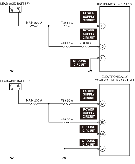
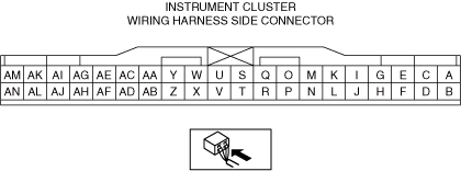
INSPECT INSTRUMENT CLUSTER POWER SUPPLY CIRCUIT FOR SHORT TO GROUND AND OPEN CIRCUIT
• Inspect the applicable circuit for a short to ground and open circuit.
• Is the circuit normal?
|
Yes
|
Go to the next step.
|
|
No
|
Repair or replace the malfunctioning location and perform the repair completion verification.
|
|
*3
|
INSPECT INSTRUMENT CLUSTER GROUND CIRCUIT FOR SHORT TO POWER SUPPLY AND OPEN CIRCUIT
• Inspect the applicable circuit for a short to power supply and open circuit.
• Is the circuit normal?
|
Yes
|
Replace the instrument cluster and perform the repair completion verification. (Open circuit in instrument cluster internal circuit)
|
|
No
|
Repair or replace the malfunctioning location and perform the repair completion verification.
|
|
4
|
VERIFY ELECTRONICALLY CONTROLLED BRAKE UNIT DTCs
• Verify the electronically controlled brake unit DTCs.
• Is a DTC displayed?
|
Yes
|
Repair the malfunctioning location according to the applicable DTC troubleshooting.
|
|
No
|
Communication error is displayed on M-MDS screen:
• Go to the next step.
Communication error is not displayed on M-MDS screen:
• Go to Step 7.
|
|
*5
|
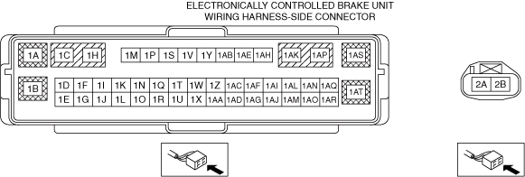
INSPECT ELECTRONICALLY CONTROLLED BRAKE UNIT POWER SUPPLY CIRCUIT FOR SHORT TO GROUND AND OPEN CIRCUIT
• Inspect the applicable circuit for a short to ground and open circuit.
• Is the circuit normal?
|
Yes
|
Go to the next step.
|
|
No
|
Repair or replace the malfunctioning location and perform the repair completion verification.
|
|
*6
|
INSPECT ELECTRONICALLY CONTROLLED BRAKE UNIT GROUND CIRCUIT FOR SHORT TO POWER SUPPLY AND OPEN CIRCUIT
• Inspect the applicable circuit for a short to power supply and open circuit.
• Is the circuit normal?
|
Yes
|
Replace the electronically controlled brake unit and perform the repair completion verification. (Open circuit in electronically controlled brake unit internal circuit)
|
|
No
|
Repair or replace the malfunctioning location and perform the repair completion verification.
|
|
7
|
INSPECT BODY CONTROL MODULE (BCM) FOR MALFUNCTION
• Perform the DTC inspection for the body control module (BCM).
• Is a DTC displayed?
|
Yes
|
Repair the malfunctioning location according to the applicable DTC troubleshooting.
|
|
No
|
Replace the instrument cluster and perform the repair completion verification.
|
|
Repair completion verification
|
VERIFY IF MALFUNCTION CAUSE IS CORRECTED
• Install/connect the part removed/disconnected during the troubleshooting procedure.
• Has the malfunction symptom been eliminated?
|
Yes
|
Complete the symptom troubleshooting.
Explain repair contents to customer.
|
|
No
|
Refer to the CAN (controller area network) malfunction diagnosis flow to inspect for a CAN communication error.
If the CAN communication is normal, perform the diagnosis from Step 1.
|