 |
am3zzw00034533
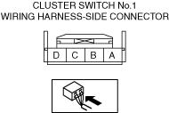
TCS OFF SWITCH INSPECTION
id041900700900
1. Disconnect the negative Lead-acid battery terminal. (See NEGATIVE LEAD-ACID BATTERY TERMINAL DISCONNECTION/CONNECTION.)
2. Disconnect the cluster switch connector. (See CLUSTER SWITCH REMOVAL/INSTALLATION.)
3. Attach the tester lead to the cluster switch wiring harness-side connector and inspect voltage or continuity according to the Terminal Voltage Table (Reference) on the table.
Terminal Voltage Table (Reference)
am3zzw00034533
|
|
Terminal |
Connected to |
Test item |
Test condition |
Specification |
Inspection item(s) |
|---|---|---|---|---|---|
|
A
|
Instrument cluster
|
Continuity
|
cluster switch terminal A—Instrument cluster B
|
Continuity
|
• Wiring harness between cluster switch terminal A and Instrument cluster terminal B
|
|
B
|
IG1 relay No.2
|
Voltage
|
Main power ON (READY off or on)
|
B+
|
• Wiring harness between cluster switch terminal B and IG1 relay No.2 terminal C
|
|
Main power OFF
|
1 V or less
|
||||
|
C
|
Instrument cluster
|
Continuity
|
cluster switch terminal C—Instrument cluster AI
|
Continuity
|
• Wiring harness between cluster switch terminal C and Instrument cluster terminal AI
|
|
D
|
Ground point
|
Continuity
|
Under any condition
|
Continuity
|
• Wiring harness between cluster switch terminal D and ground point
|