 |
a30zzn00001571
ELECTRONICALLY CONTROLLED BRAKE SYSTEM [(E)]
id0419007013x2
Outline
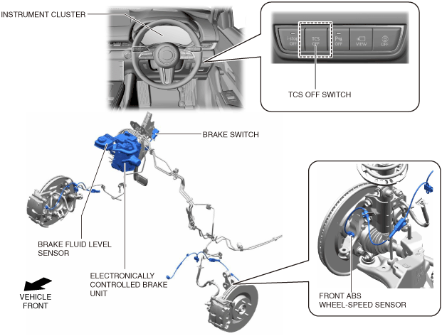
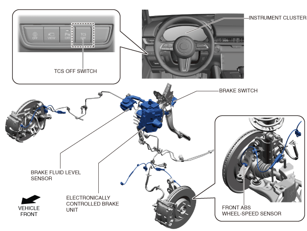
Structural view
Vehicle front (L.H.D.)
a30zzn00001571
|
Vehicle front (R.H.D.)
a30zzn00001506
|
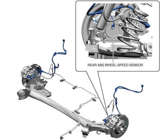
Vehicle rear
a30jjn00000197
|
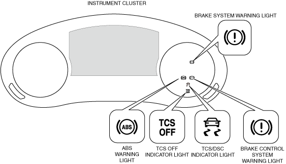
Warning lights/indicator lights
a30zzn00000866
|
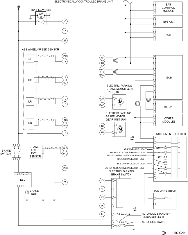
System Wiring Diagram
a30zzn00001572
|
Construction
|
Part name |
Function |
|||
|---|---|---|---|---|
|
Electronically controlled brake unit
|
CM part
|
• Calculates the signals from each sensor, controls the brake fluid pressure applied to each wheel, and executes each function of the DSC system (ABS, EBD, TCS, DSC, brake assist control, Hill Launch Assist (HLA), and the secondary collision reduction system).
• Performs regenerative braking coordinated control by communication with the PCM, and controls the brake fluid pressure according to the change in the regenerative braking force by the resistance generated by the electric motor.
• Executes AUTOHOLD based on the signal from each module and the AUTOHOLD switch.
• Outputs the torque reduction request signal, vehicle speed signal, and DSC system warning control information via CAN communication.
• If a malfunction occurs in a system, it controls the on-board diagnostic system and the fail-safe function.
|
||
|
HU part
|
• Based on the signal from the CM part of the electronically controlled brake unit, it executes the increase, decrease or maintenance of the brake fluid pressure applied to each wheel, and the normal brakes and each function of the DSC system (ABS, EBD, TCS, DSC, brake assist function, Hill Launch Assist (HLA), and the secondary collision reduction system).
|
|||
|
Master Cylinder
|
• Converts the brake pedal depression amount by the driver to brake fluid pressure and sends it to the stroke simulator.
|
|||
|
Stroke simulator
|
• Generates a brake pedal stroke and brake pedal depression response according to the brake pedal depression amount by the driver.
|
|||
|
Linear actuator
|
• Generates the necessary brake fluid pressure according to the control signal from the CM part of the electronically controlled brake unit.
|
|||
|
Stroke sensor
(Built-into electronically controlled brake unit)
|
• Detects the brake pedal depression amount by the driver.
|
|||
|
Brake fluid pressure sensor
(Built-into electronically controlled brake unit)
|
• Detects the brake fluid pressure generated by the master cylinder and the actuator.
|
|||
|
PCM
|
• Controls the regenerative braking force during vehicle speed deceleration by communicating with the electronically controlled brake unit.
• Controls the electric motor output during DSC and TCS operation based on the signal from the electronically controlled brake unit.
• Transmits the target gear position and selector lever position information to the electronically controlled brake unit via CAN communication.
|
|||
|
EPS CM
|
• Transmits the steering angle to the electronically controlled brake unit via CAN communication.
|
|||
|
SAS control module
|
• Transmits the vehicle lateral-G (vehicle lateral acceleration speed), yaw rate (vehicle turning angle speed), and longitudinal-G (vehicle longitudinal acceleration speed) to the electronically controlled brake unit via CAN communication.
|
|||
|
ABS wheel-speed sensor
|
• Detects the rotation condition of each wheel and transmits it to the electronically controlled brake unit.
|
|||
|
Brake light unit
|
• Transmits the brake light condition (on/off) to the electronically controlled brake unit.
|
|||
|
TCS OFF switch
|
• Transmits the TCS control permit/inhibit intention by the driver to the electronically controlled brake unit.
|
|||
|
TCS OFF indicator light
|
• Notifies the driver that the TCS/DSC control is inhibited by the TCS OFF switch.
|
|||
|
Brake system warning light
|
• Notifies the driver that the ABS or EBD is malfunctioning.
• Notifies the driver that the brake fluid level is low.
• Notifies the driver that the brake system operation is abnormal.
|
|||
|
ABS warning light
|
• Notifies the driver that the ABS is malfunctioning.
|
|||
|
TCS/DSC operation indicator light
|
• Notifies the driver that the TCS is operating (drive wheel is spinning).
• Notifies the driver that the DSC is operating (vehicle is skidding).
• Notifies the driver that the DSC system is malfunctioning.
|
|||
|
AUTOHOLD SWITCH
|
• Switches the AUTOHOLD between operation/non-operation.
|
|||
|
AUTOHOLD operation indicator light
|
• Notifies the driver that the AUTOHOLD is operating.
|
|||
|
Brake fluid level sensor
|
• Detects the brake fluid level and transmits it to the electronically controlled brake unit.
|
|||
|
Electric parking brake switch
|
||||
|
Electric parking brake motor gear unit
|
||||
|
Electric parking brake indicator light
|
||||
|
Brake control system warning light
|
||||