 |
a30zzw00000896
SELECTOR LEVER INSPECTION [A71M]
id0526a7000800
Voltage Inspection
1. Disconnect the negative lead-acid battery terminal. (See NEGATIVE LEAD-ACID BATTERY TERMINAL DISCONNECTION/CONNECTION.)
2. Remove the selector lever knob. (See SELECTOR LEVER REMOVAL/INSTALLATION [A71M].)
3. Remove the shift panel. (See SHIFT PANEL REMOVAL/INSTALLATION.)
4. Connect the negative lead-acid battery terminal. (See NEGATIVE LEAD-ACID BATTERY TERMINAL DISCONNECTION/CONNECTION.)
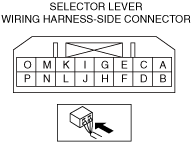
5. Verify that the voltages of each of the terminals are as indicated in the terminal voltage table (reference).
Terminal Voltage Table (Reference)
a30zzw00000896
|
|
Terminal |
Signal |
Connection |
Measurement condition |
Voltage (V) |
Inspection items |
|---|---|---|---|---|---|
|
A
|
IG1
|
IG1 relay No. 2
|
Main power ON (READY off or on)
|
B+
|
• Wiring harness (A—IG1 relay No. 2 C)
|
|
Main power OFF
|
1.0 or less
|
||||
|
B
|
CAN_L_PBLC1
|
CAN related module
|
Because this terminal is for communication, determination using terminal voltage inspection is not possible. Perform inspection using the DTC inspection.
|
||
|
C
|
BATT
|
Lead-acid battery
|
Continuous
|
B+
|
• Wiring harness (C—lead-acid battery)
|
|
D
|
CAN_H_PBLC1
|
CAN related module
|
Because this terminal is for communication, determination using terminal voltage inspection is not possible. Perform inspection using the DTC inspection.
|
||
|
E
|
—
|
—
|
—
|
—
|
—
|
|
F
|
CAN_L_PBLC2
|
CAN related module
|
Because this terminal is for communication, determination using terminal voltage inspection is not possible. Perform inspection using the DTC inspection.
|
||
|
G
|
GND
|
ground point
|
Continuous
|
1.0 or less
|
• Wiring harness (G—ground point)
|
|
H
|
CAN_H_PBLC2
|
CAN related module
|
Because this terminal is for communication, determination using terminal voltage inspection is not possible. Perform inspection using the DTC inspection.
|
||
|
I
|
Indicator_R
|
Indicator
|
R position
|
1.0 or less
|
• Wiring harness (I—indicator D)
|
|
Other than R position
|
B+
|
||||
|
J
|
—
|
—
|
—
|
—
|
—
|
|
K
|
IND_Ilumi_power
|
Indicator
|
Main power ON (READY off or on)
|
B+
|
• Wiring harness (K—indicator A)
|
|
Main power OFF
|
|
|
|||
|
L
|
Indicator_N
|
Indicator
|
N position
|
1.0 or less
|
• Wiring harness (L—indicator E)
|
|
Other than N position
|
B+
|
||||
|
M
|
Indicator_P
|
Indicator
|
P position
|
1.0 or less
|
• Wiring harness (M—indicator C)
|
|
Other than P position
|
B+
|
||||
|
N
|
—
|
—
|
—
|
—
|
—
|
|
O
|
Back_Ilumi_power
|
Indicator
|
Main power ON (READY off or on)
|
B+
|
• Wiring harness (O—indicator B)
|
|
P
|
Indicator_D
|
Indicator
|
D position
|
1.0 or less
|
• Wiring harness (P—indicator F)
|
|
Other than D position
|
B+
|
||||
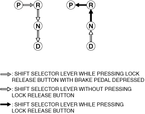
Operation Inspection
1. Switch the main power ON (READY on).
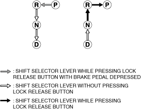
2. Inspect the selector lever as follows:
L.H.D.
a30zzw00000900
|
R.H.D.
a30zzw00005650
|