REFRIGERANT CHARGING
id071000700400
-
Caution
-
• Do not use a different type of refrigerant or charge beyond the specified level. Otherwise, cooling ability will be lowered and the cooling system parts could be damaged.
-
Note
-
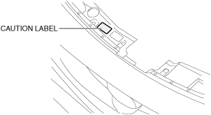
• When recovering/charging the refrigerant, verify the type of refrigerant and the specified refrigerant amount on the caution label.
|
Refrigerant type
|
Specified refrigerant amount (reference)
|
|
HFO-1234yf (R-1234yf)
|
1,185—1,235 g {41.80—43.56 oz}
|
Refrigerant (HFO-1234yf) recovery
1. Switch the main power OFF and wait for 100 s or more.
2. Correctly collect the refrigerant following the instructions for the chlorofluorocarbon (CFC) recovery machine being used.
Adding compressor oil
-
Caution
-
<<High voltage>>
• Do not add fluorescent agent into the refrigeration cycle. Otherwise, electrical insulation of the air conditioner system may deteriorate and high voltage electrical leakage may occur.
1. When collecting the refrigerant, weigh the exhausted compressor oil.
2. When adding refrigerant, add new compressor oil to the refrigeration cycle equivalent in weight to the exhausted amount.
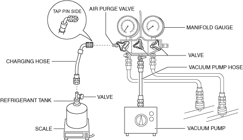
Preparation for charging
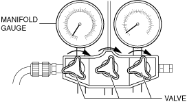
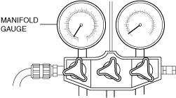
1. Close all the valves of the manifold gauge.
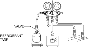
2. Close the refrigerant tank valve.
3. Install the manifold gauge set. (See MANIFOLD GAUGE SET CONNECTION.)
4. Attach the vacuum pump hose to the manifold gauge.
5. Attach the charging hose (tap pin side) to the air purge valve of the manifold gauge.
6. Attach the charging hose (no-tap pin side) to the refrigerant tank.
7. Place the refrigerant tank on the scale.
8. Attach the vacuum pump hose to the vacuum pump.
9. Perform vacuum discharging. (See Vacuum discharging.)
Vacuum discharging
1. Switch the main power OFF and wait for 100 s or more.
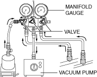
2. Open all valves of the manifold gauge.
3. Start the vacuum pump and perform vacuum discharging on the refrigeration cycle for 15 min.
4. Verify that high- and low-pressure side readings of the manifold gauge are at -0.1 MPa {-1 kgf/cm2, -15 psi}.
5. Stop the vacuum pump.
-
Caution
-
• If the manifold gauge valves are left open, vacuum pump oil will backflow into the refrigeration cycle and cause the cooling performance to lower. After stopping the vacuum pump, close the manifold gauge valves immediately.
6. Close all the valves of the manifold gauge.
7. Wait for 5 min after stopping the vacuum pump, and perform an airtightness check for the refrigerant system. (See Air tightness check.)
Air tightness check
1. Verify that the manifold gauge reading has not changed.
-
Refrigerant (HFO-1234yf) charging
-
Warning
-
• If the valve on the high pressure side is opened while the electric compressor is running, highly pressurized refrigerant could backflow into the refrigerant tank and cause damage. Never open the valve on the high pressure side.
1. Open the refrigerant tank.
2. Measure the weight of the refrigerant tank.
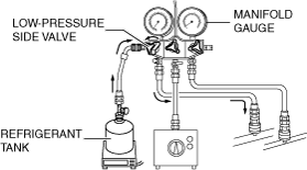
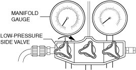
3. Open the low pressure valve of the manifold gauge.
4. Verify that low-pressure side readings of the manifold gauge is at 0.1 MPa {1 kgf/cm2, 15 psi}.
5. Close the low pressure side valve of the manifold gauge.
6. Inspect for gas leakage from the piping connection using a gas leak detector or a fluorescent agent-detecting UV black light.
-
• If there is no gas leakage, go to Step 7.
• If there is gas leakage, tighten the piping connection to the specified torque, then go to the next step.
7. Inspect again for gas leakage from the piping connection using a gas leak detector or a fluorescent agent-detecting UV black light.
-
• If there is no gas leakage, go to the next step.
-
Caution
-
• Never start the electric compressor while the valve on the high pressure side is open. If the electric compressor is started while the manifold gauge valve on the high pressure side is open, highly pressurized refrigerant could backflow into the refrigerant tanks and cause damage.
8. Open the low pressure valve of the manifold gauge.
-
Caution
-
• If the refrigerant system is charged with the refrigerant tank upside down, liquid refrigerant will be charged into the system, and the electric compressor could become highly pressurized and damaged. Never charge refrigerant with the refrigerant tank upside down.
9. Charge with refrigerant until the weight of refrigerant tank has decreased 600 g {21.2 oz} from the amount in Step 2.
10. Close the low pressure side valve of the manifold gauge.
11. Switch the main power ON (READY ON) and activate the electric compressor.
12. Open the low pressure side valve of the manifold gauge and inject refrigerant until the weight of the refrigerant tank decreases from the amount in Step 2 to the normal amount.
-
Caution
-
• If the refrigerant system is charged with the refrigerant tank upside down, liquid refrigerant will be charged into the system, and the electric compressor could become highly pressurized and damaged. Never charge refrigerant with the refrigerant tank upside down.
13. Close the low pressure side valve of the manifold gauge.
14. Switch the main power OFF.
15. Perform the leak test. (See Leak test.)
Leak test
-
Caution
-
• Looking directly at a fluorescent agent-detecting UV black light may cause injury to the eyes. Do not look directly into the light of a fluorescent agent-detecting UV black light.
-
Note
-
• Because fluorescent agents are in the refrigeration cycle, the leak test can be performed with a fluorescent agent-detecting UV black light.
1. Inspect for gas leakage from the piping connection using a gas leak detector or a fluorescent agent-detecting UV black light.
-
• If there is no gas leakage, go to Step 3.
• If there is gas leakage, tighten the piping connection to the specified torque, then go to the next step.
2. Inspect for gas leakage from the piping connection using a gas leak detector or a fluorescent agent-detecting UV black light.
-
• If there is no refrigerant leakage, perform the procedure from the evacuation again. (See
Vacuum discharging.)
3. Remove the quick coupler from the charging valve located on the high and low pressure lines.
4. Attach the cap to the charging valve.