 |
a30jjw00000137
BLOWER MOTOR INSPECTION
id071100700000
1. Disconnect the negative lead-acid battery terminal. (See NEGATIVE LEAD-ACID BATTERY TERMINAL DISCONNECTION/CONNECTION.)
2. Remove the blower motor. (See BLOWER MOTOR REMOVAL/INSTALLATION.)
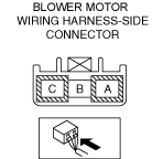
3. Connect the blower motor connector.
4. Connect the negative lead-acid battery terminal. (See NEGATIVE LEAD-ACID BATTERY TERMINAL DISCONNECTION/CONNECTION.)
5. Connect the negative (-) lead of the tester to body ground.
6. Insert the positive (+) lead of the tester into each climate control unit terminal and measure the voltage according to the terminal voltage table.
Terminal Voltage Table (Reference)
a30jjw00000137
|
|
Terminal
|
Signal name
|
Connected to
|
Measurement condition
|
Voltage (V)
|
Inspection item (s)
|
|
A
|
GND
|
Body ground
|
Under any condition
|
Approx. 0
|
• GND point
• Related wiring harness
|
|
B
|
S1
|
Dash-electrical supply unit
|
• Related wiring harness
• Dash-electrical supply unit
|
||
|
C
|
BATT
|
Blower relay
|
Under any condition
|
B+
|
• Lead-acid battery
• Blower relay
|
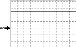
Blower fan speed control signal
Fan stopped
ac9uuw00009649
|
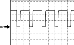
Lo
a30jjw00000138
|
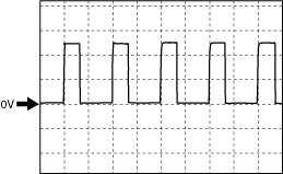
Hi
a30jjw00000139
|