a30zzn00001207
|
FULL-AUTO AIR CONDITIONER SYSTEM [FULL-AUTO AIR CONDITIONER]
id0740a1700400
Outline
Function
a30zzn00001207
|
a30zzn00001060
|
Airflow temperature control
Airflow volume control
Airflow mode control
Air intake control
Electric compressor control
Heat pump system control
PTC heater control
ECO mode control
Heated steering wheel control (With heated steering wheel)
Seat warmer control (With seat warmer)
Climate control timer control
Control for remote climate control (when Connected Service is enabled)
Structure/construction
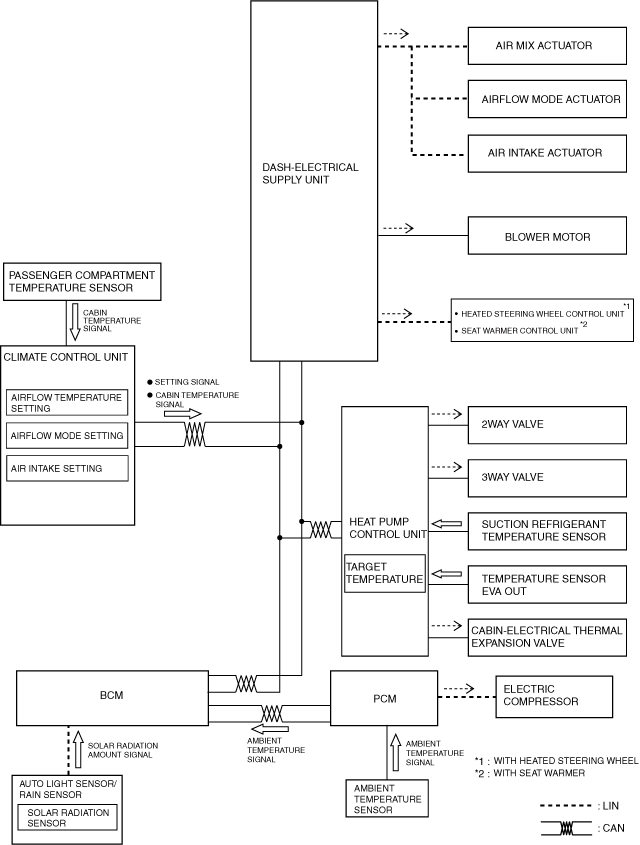
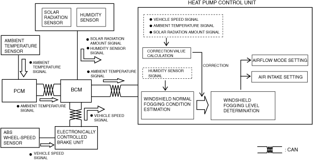
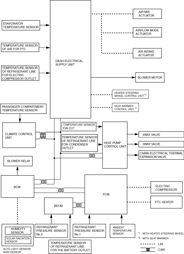
Block Diagram
a30zzn00001092
|
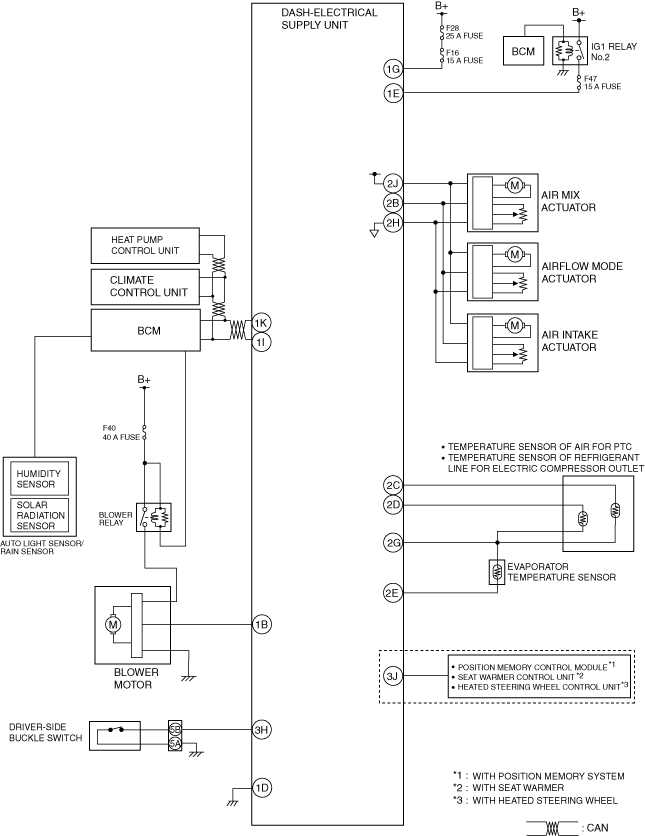
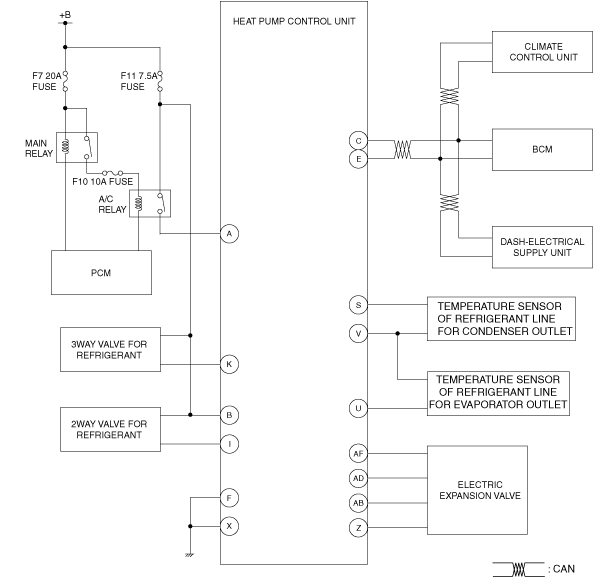
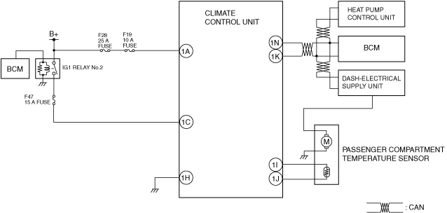
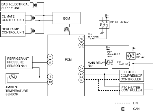
System wiring diagram
a30zzn00001083
|
a30zzn00001084
|
a30zzn00001208
|
a30zzn00001086
|
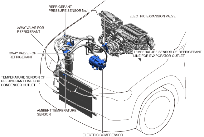
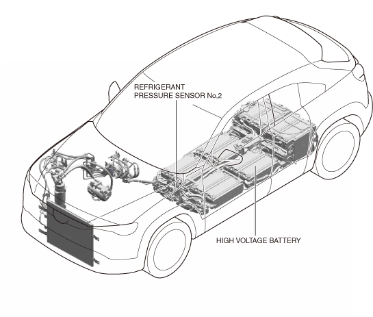
Structural view
L.H.D.
a30zzn00001218
|
R.H.D.
a30zzn00002238
|
a30jjn00000300
|
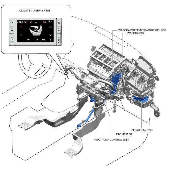
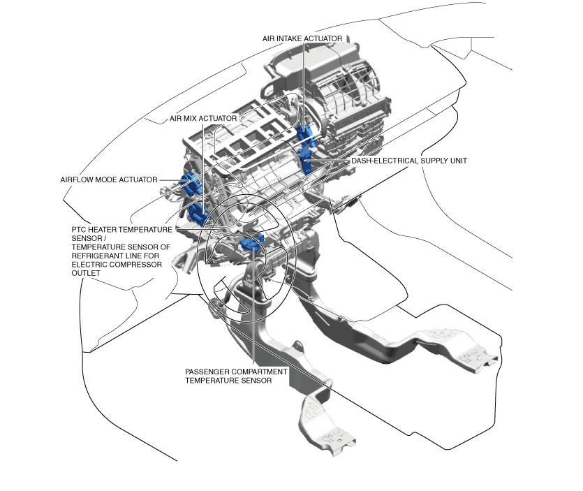
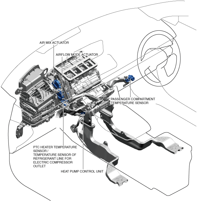
Structural view (L.H.D.)
a30zzn00001058
|
a30jjn00000304
|
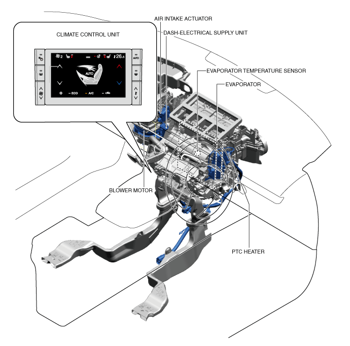
Structural view (R.H.D.)
a30zzn00002239
|
a30zzn00002240
|
Operation
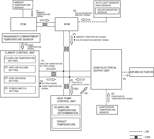
Airflow temperature control
1. When the airflow temperature setting is operated with the main power switched ON (Ready on), the climate control unit sends an airflow temperature setting signal (1) to the heat pump control unit.
2. Based on the signals (2) from each sensor which changes according to the airflow temperature setting and the vehicle conditions, the heat pump control unit performs airflow temperature determination (3).
3. The heat pump control unit sends an electric compressor speed command signal and a PTC heater operation signal to the PCM, and sends an air mix actuator operation request signal (4) to the dash-electrical supply unit, based on the airflow temperature determination results and corrections
For the operation of the electric compressor and the PTC heater, refer to the [Electric compressor control] and [PTC heater control]
4. The dash-electrical supply unit receives the air mix actuator operation request signal from the heat pump control unit and sends an air mix actuator operation signal (5) to the air mix actuator.
a30zzn00001047
|
Airflow volume control
1. When the main power is switched ON (READY off or on), the body control module (BCM) turns the blower relay on (1), and the blower motor goes on operation standby.
2. When the airflow volume setting is operated, the climate control unit sends an airflow volume setting signal (2) to the heat pump control unit.
3. Based on the airflow volume setting and the signals (3) from each sensor, the heat pump control unit performs airflow volume determination (4).
4. The heat pump control unit sends a blower speed signal (5) to the dash-electrical supply unit based on the airflow volume determination results and corrections.
5. The dash-electrical supply unit receives the blower speed signal from the heat pump control unit and sends a blower motor operation signal (6) to the blower fan controller.
6. The blower motor changes the rotation speed according to the blower fan controller (7) control.
a30zzn00001048
|
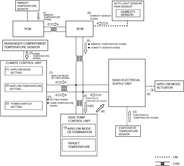
Airflow mode control
1. When the airflow mode setting is operated with the main power switched ON (Ready off or on), the climate control unit sends an airflow mode setting signal (1) to the heat pump control unit.
2. Based on the airflow mode setting and the signals (2) from each sensor which changes according to the vehicle conditions, the heat pump control unit performs airflow mode determination (3).
3. The heat pump control unit sends a mode actuator operation request signal (4) to the dash-electrical supply unit based on the airflow mode determination results and corrections.
4. The dash-electrical supply unit receives the mode actuator operation request signal from the heat pump control unit and sends a mode actuator operation signal (5) to the mode actuator.
a30zzn00001049
|
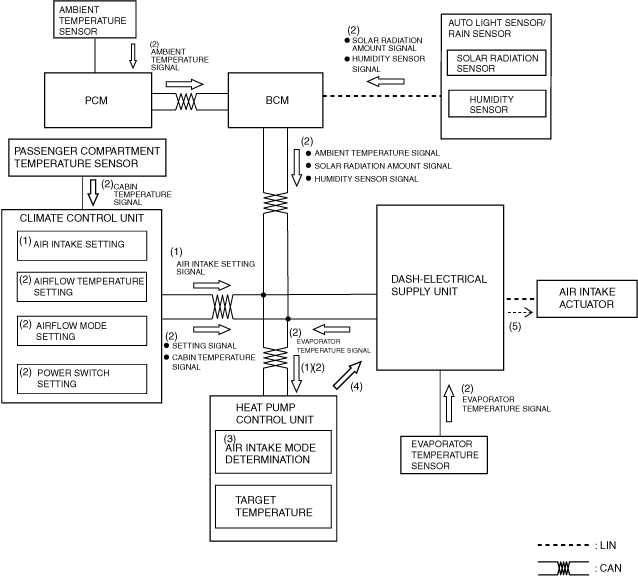
Air intake control
1. When the air intake setting is operated with the main power switched ON (Ready off or on), the climate control unit sends an air intake setting signal (1) to the dash-electrical supply unit.
2. Based on the signals (2) from each sensor which changes according to the vehicle conditions, the heat pump control unit performs air intake mode determination (3).
3. The heat pump control unit sends an air intake actuator operation request signal (4) to the dash-electrical supply unit based on the air intake mode determination results and corrections.
4. The dash-electrical supply unit receives the air intake actuator operation request signal from the heat pump control unit and sends an air intake actuator operation signal (5) to the air intake actuator.
a30zzn00001050
|
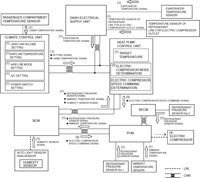
Electric compressor control
1. Based on the signals (1) from each sensor which changes according to the target temperature, the climate control setting, and the vehicle conditions, the heat pump control unit performs electric compressor mode determination (2).
2. The heat pump control unit sends (3) an electric compressor speed command signal to the PCM according to the electric compressor mode determination results and corrections.
3. The PCM operates the electric compressor based on the electric compressor speed command signal from the heat pump control unit.
a30zzn00001087
|
Heat pump system control
|
Refrigerant control mode |
2way valve for refrigerant |
3way valve for refrigerant |
|---|---|---|
|
Cooling control
|
OFF (OPEN)
|
ON (accumulator side: OPEN)
|
|
Heating control
|
ON (CLOSED)
|
OFF (electric expansion valve side: OPEN)
|
|
Defrosting control
|
OFF (OPEN)
|
OFF (electric expansion valve side: OPEN)
|
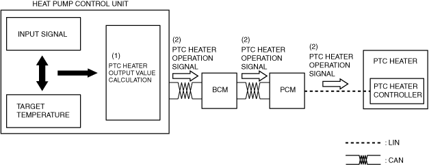
PTC heater control
1. The heat pump control unit calculates (1) the PTC heater output value (heat generation amount and operation time) based on the input signal from each sensor and the target temperature from the dash-electrical supply unit.
2. The heat pump control unit outputs (2) the PTC heater operation signal to the PTC heater controller based on the calculated PTC heater output value.
a30zzn00001088
|
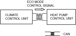
ECO mode control
1. When the ECO mode icon is pressed, the heater control unit determines that the ECO mode is on and sends an ECO mode control signal to the heat pump control unit.
2. After receiving the ECO mode control signal, the heat pump control unit performs climate control suppressing the power consumption by the climate control system.
a30zzn00000857
|
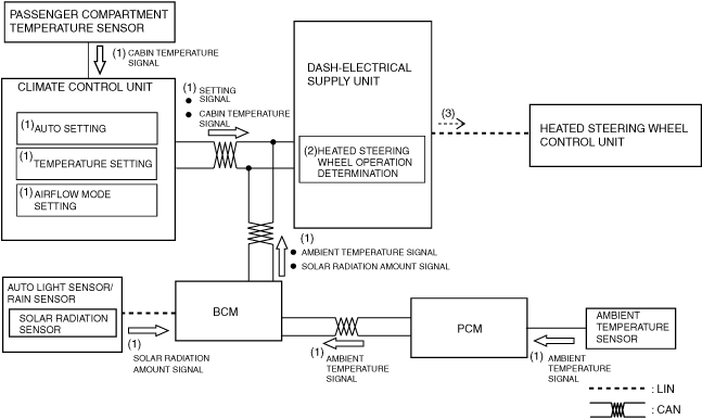
Heated steering wheel control (With heated steering wheel)
a30zzn00001089
|
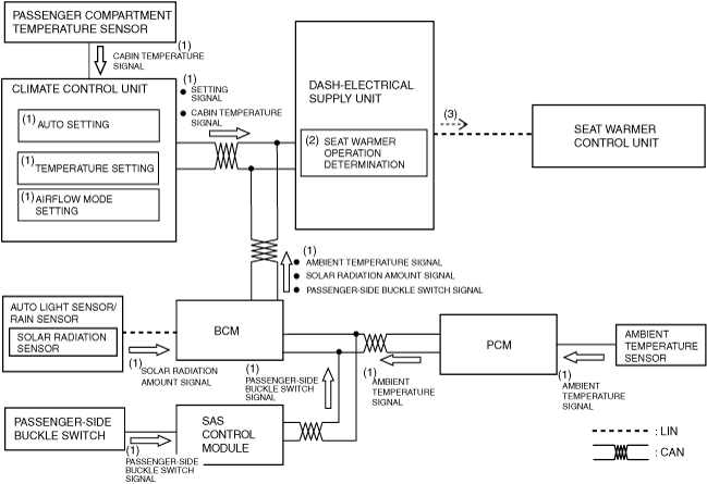
Seat warmer control (With seat warmer)
a30zzn00001090
|
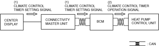
Climate control timer control
1. When the climate control timer is set on the center display, the climate control timer setting signal (1) is sent to the BCM via the connectivity master unit (CMU).
2. When the climate control timer reaches the start time, the BCM sends a climate control timer operation signal (2) to the heat pump control unit.
3. After receiving the climate control timer operation signal, the heat pump control unit performs climate control according to the settings made.
a30zzn00000858
|
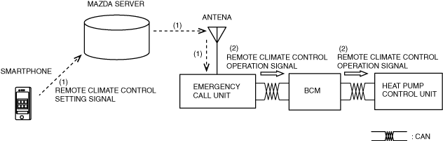
Control for remote climate control (when Connected Service is enabled)
1. When the remote climate control is set using a Smartphone,
a remote climate control setting signal (1) is sent to the emergency call unit.
2. When the emergency call unit receives the remote climate control setting signal, it sends a remote climate control operation signal (2) to the heat pump control unit via the BCM.
3. After receiving the remote climate control operation signal, the heat pump control unit performs climate control according to the settings made.
a30zzn00000859
|