 |
ac30zw00005006
POWER OUTER MIRROR INSPECTION
id091200703100
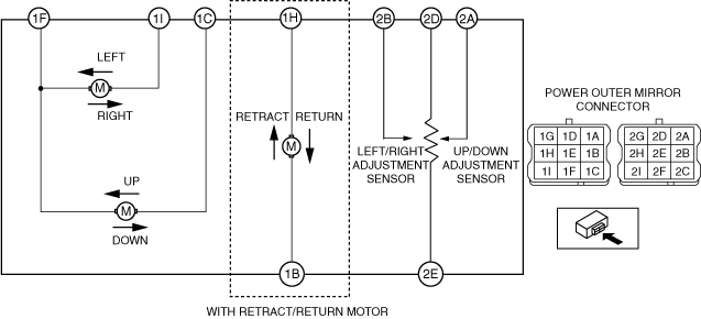
Up/down Adjustment Motor, Left/right Adjustment Motor, Retract/return Motor, Up/down Adjustment Sensor, Left/right Adjustment Sensor
1. Disconnect the negative lead-acid battery terminal. (See NEGATIVE LEAD-ACID BATTERY TERMINAL DISCONNECTION/CONNECTION.)
2. Remove the power outer mirror. (See POWER OUTER MIRROR REMOVAL/INSTALLATION.)
3. Apply battery positive voltage and connect the ground to the power outer mirror terminals and inspect the power outer mirror operation.
ac30zw00005006
|
|
Mirror operation direction |
Battery positive voltage connect terminal |
Ground connect terminal |
|---|---|---|
|
Up
|
1C
|
1F
|
|
Down
|
1F
|
1C
|
|
Left
|
1I
|
1F
|
|
Right
|
1F
|
1I
|
|
Retract
|
1B
|
1H
|
|
Return
|
1H
|
1B
|
4. Verify the resistance of the up/down adjustment sensor and the left/right adjustment sensor for the power outer mirror.
Outer mirror glass (RH)
|
Mirror operation |
Resistance (Ω) |
Terminal |
|---|---|---|
|
Outer mirror glass (RH) moved to upper direction limit
|
Approx. 0
|
2A—2D
|
|
Outer mirror glass (RH) moved to lower direction limit
|
Approx. 5000
|
2A—2D
|
|
Outer mirror glass (RH) moved to left direction limit
|
Approx. 5000
|
2B—2D
|
|
Outer mirror glass (RH) moved to right direction limit
|
Approx. 0
|
2B—2D
|
Outer mirror glass (LH)
|
Mirror operation |
Resistance (Ω) |
Terminal |
|---|---|---|
|
Outer mirror glass (LH) moved to upper direction limit
|
Approx. 0
|
2A—2D
|
|
Outer mirror glass (LH) moved to lower direction limit
|
Approx. 5000
|
2A—2D
|
|
Outer mirror glass (LH) moved to left direction limit
|
Approx. 0
|
2B—2D
|
|
Outer mirror glass (LH) moved to right direction limit
|
Approx. 5000
|
2B—2D
|
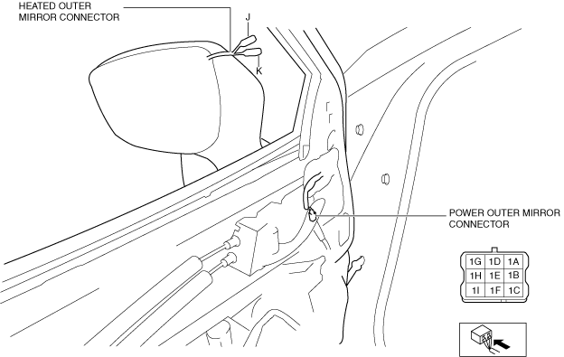
Heated Outer Mirror Inspection (With Heated Outer Mirror)
1. Disconnect the negative lead-acid battery terminal. (See NEGATIVE LEAD-ACID BATTERY TERMINAL DISCONNECTION/CONNECTION.)
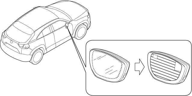
2. Remove the outer mirror glass. (See OUTER MIRROR GLASS REMOVAL.) (See OUTER MIRROR GLASS INSTALLATION
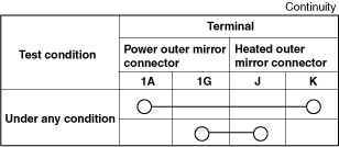
3. Verify that the continuity between heated outer mirror connector terminals is as indicated in the table.
a30zzw00000911
|
a30zzw00004576
|
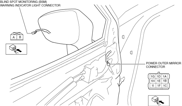
Blind Spot Monitoring (BSM) Warning Indicator Light Inspection
1. Disconnect the negative lead-acid battery terminal. (See NEGATIVE LEAD-ACID BATTERY TERMINAL DISCONNECTION/CONNECTION.)
2. Remove the outer mirror glass. (See OUTER MIRROR GLASS REMOVAL.) (See OUTER MIRROR GLASS INSTALLATION.)
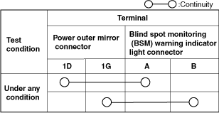
3. Verify that the continuity between blind spot monitoring (BSM) warning indicator light connector terminals is as indicated in the table.
a30zzw00004760
|
a30zzw00004761
|
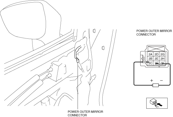
Auto-Dimming Outer Mirror Inspection (With Auto-Dimming Outer Mirror)
1. Disconnect the negative lead-acid battery terminal. (See NEGATIVE LEAD-ACID BATTERY TERMINAL DISCONNECTION/CONNECTION.)
2. Disconnect the power outer mirror connector. (See POWER OUTER MIRROR REMOVAL/INSTALLATION.)
3. Connect the power outer mirror connector terminal 2C to a dry cell battery's plus (+) terminal (1.2 V) and terminal 2F to its minus terminal.
a30zzw00004747
|
a30zzw00005527
|
4. If there is any malfunction, inspect the outer mirror glass. (See OUTER MIRROR GLASS INSPECTION.)