 |
a30zzb00000025
FRONT SIDE FRAME (PARTIAL CUTTING) REMOVAL [PANEL REPLACEMENT]
id098008742100
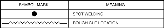
Symbol Mark
a30zzb00000025
|
Removal Procedure
LH
1. Refer to [DAMAGED VEHICLE HANDLING] and [HIGH VOLTAGE SERVICE CAUTIONS] in the general information, implement the necessary measures, and then start the procedure.(See DAMAGED VEHICLE HANDLING [(E)].) (See HIGH VOLTAGE SERVICE CAUTIONS.)
2. Remove the bumper bracket. (See BUMPER BRACKET REMOVAL [PANEL REPLACEMENT].)
3. Remove the light bracket. (See LIGHT BRACKET REMOVAL [PANEL REPLACEMENT].)
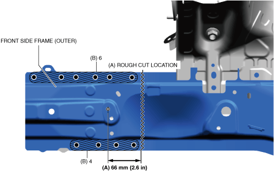
4. Rough cut the location in area A shown in the figure.
5. Drill the spot welds in the 10 locations in area B shown in the figure.
a30zzb00000079
|
6. Remove the front side frame (outer).
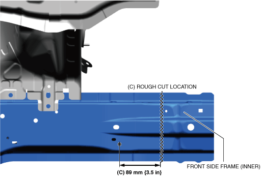
7. Rough cut the location in area C shown in the figure.
a30zzb00000083
|
8. Remove the front side frame (inner).
RH
1. Refer to [DAMAGED VEHICLE HANDLING] and [HIGH VOLTAGE SERVICE CAUTIONS] in the general information, implement the necessary measures, and then start the procedure.(See DAMAGED VEHICLE HANDLING [(E)].) (See HIGH VOLTAGE SERVICE CAUTIONS.)
2. Remove the bumper bracket. (See BUMPER BRACKET REMOVAL [PANEL REPLACEMENT].)
3. Remove the light bracket. (See LIGHT BRACKET REMOVAL [PANEL REPLACEMENT].)
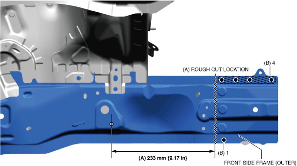
4. Rough cut the location in area A shown in the figure.
5. Drill the spot welds in the 5 locations in area B shown in the figure.
a30zzb00000084
|
6. Remove the front side frame (outer).
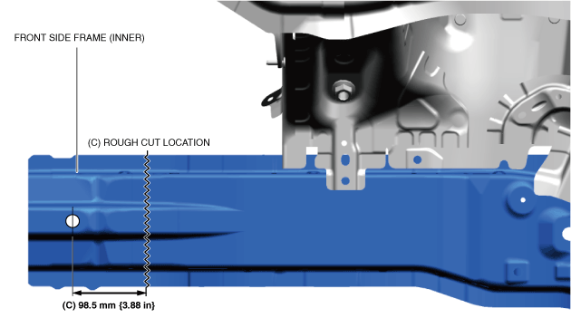
7. Rough cut the location in area C shown in the figure.
a30zzb00000085
|
8. Remove the front side frame (inner).