ac5uun00002862
|
MULTIPLEX COMMUNICATION SYSTEM [(E)]
id1000000014x2
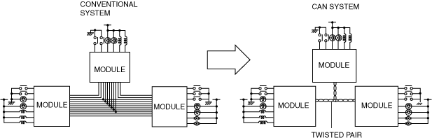
Outline
ac5uun00002862
|
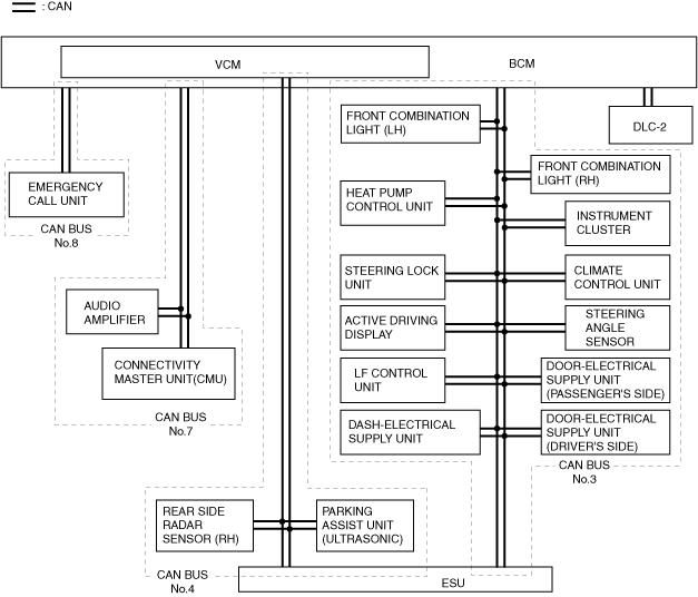
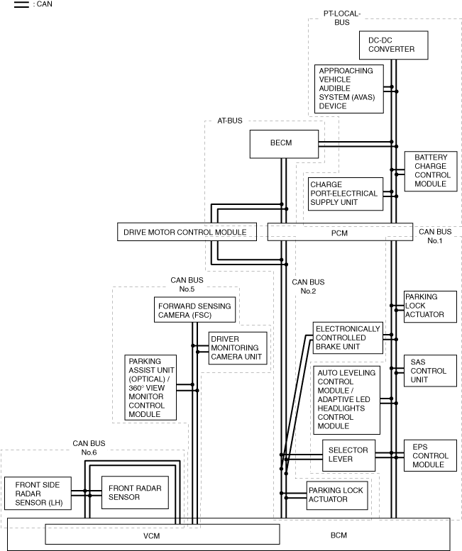
System Wiring Diagram
CAN communication (L.H.D.)
a30zzn00002591
|
a30zzn00002592
|
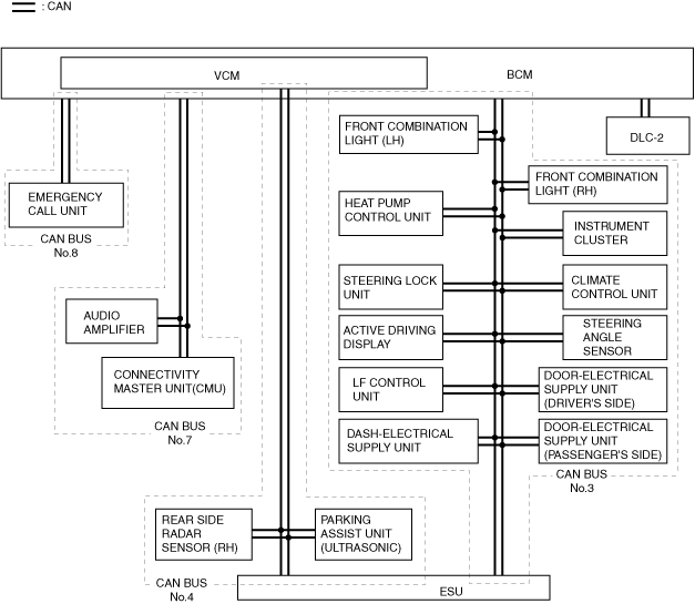
CAN communication (R.H.D.)
a30zzn00002593
|
a30zzn00002594
|
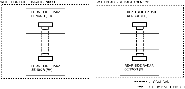
Local CAN
a30zzn00001061
|
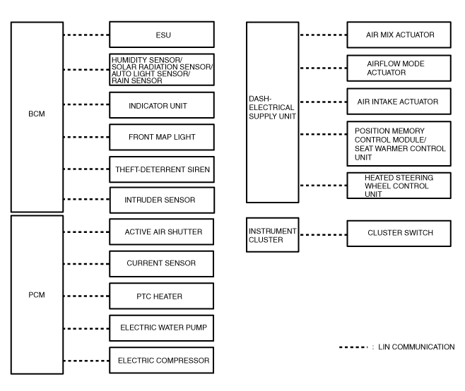
LIN communication
a30zzn00000810
|
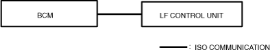
ISO communication
a30zzn00001081
|
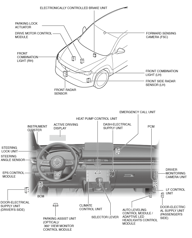
Structural View
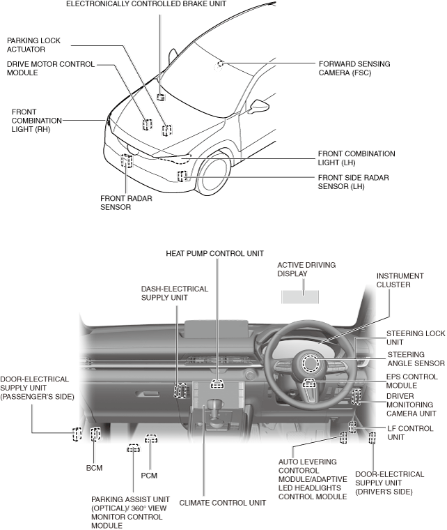
L.H.D.
a30zzn00000740
|
a30zzn00000741
|
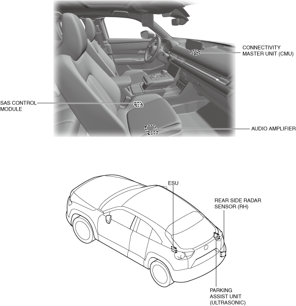
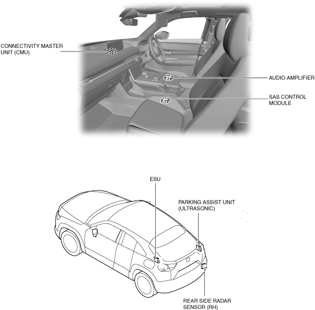
R.H.D.
a30zzn00002249
|
a30zzn00002250
|
Function
CAN (controller area network) system
Local CAN
LIN communication
ISO communication
Construction
CAN
Local CAN
LIN communication
ISO communication