ONBOARD CHARGER INSPECTION [(E)]
id3040001040e1
-
Warning
-
<<High voltage>>
• If the necessary measures are not taken before servicing an electric vehicle, it could cause electrical shock and result in serious injury or, in the worst case, death. Before servicing the electric vehicle, refer to [HIGH VOLTAGE SERVICE CAUTIONS] in the general information and implement the necessary measures. (See
HIGH VOLTAGE SERVICE CAUTIONS.)
High Voltage Part Inspection And Removal/Installation Notes
-
Warning
-
<<High voltage>>
• If necessary measures such as wearing the correct protective gear are not taken when inspecting or removing/installing the high voltage parts, it could cause electrical shock and result in serious injury or, in the worst case, death.
• Before inspecting or removing/installing the high voltage parts, refer to [HIGH VOLTAGE SERVICE CAUTIONS] in the general information and [High Voltage Part Inspection and Removal/Installation Notes] of the high voltage system service cautions and implement the necessary measures and preparations. (See
HIGH VOLTAGE SERVICE CAUTIONS.) (See
HIGH VOLTAGE SYSTEM SERVICE CAUTIONS.)
Insulation Inspection
-
Warning
-
<<High voltage>>
• Wear insulating gloves when working on a high voltage system.
1. Remove the service plug. (See SERVICE PLUG REMOVAL/INSTALLATION.)
-
Warning
-
<<High voltage>>
• For the insulation resistance tester usage, refer to the insulation resistance tester instruction manual. Otherwise, electrocution could result from the voltage generated by the insulation resistance tester.
-
Caution
-
<<High voltage>>
• Use an insulation resistance tester using a testing range of 250 V or less because the high voltage applied by the insulation resistance tester may damage the parts.
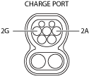
2. Wear insulating gloves and measure the insulation resistance between normal charging port terminals 2B and 2D using an insulation resistance tester (250 V range).
-
• If not within the standard, go to the next step.
• If within the standard, wear insulating gloves, connect the high voltage system connector that was disconnected, and then perform a DTC inspection.
Insulation resistance
-
• 80 kΩ or more
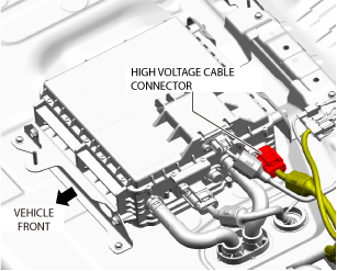
3. Wear insulating gloves and disconnect the high voltage system connector of the onboard charger shown in the figure. (See ONBOARD CHARGER REMOVAL/INSTALLATION.)
4. Verify that there is no continuity between normal charging port terminal 2B and 2D.
-
DTC inspection
1. Connect the M-MDS to the DLC-2.
2. Perform the PCM and battery charge control module DTC inspection using the M-MDS, and if a battery charge control module related DTC is output, repair the malfunctioning location according to the applicable DTC troubleshooting. (See DTC INSPECTION.) (See DTC TABLE [PCM (e-SKYACTIV)].) (See DTC TABLE [BATTERY CHARGE CONTROL MODULE (e-SKYACTIV)].)