 |
a30zzn00000890
CHARGING SYSTEM [(E)]
id3042001000e1
Outline
Normal charging
Quick charging
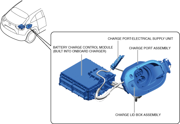
Structural View
a30zzn00000890
|
|
Part name |
Reference |
|---|---|
|
Charge port assembly
|
|
|
Charge lid box assembly
|
|
|
Battery charge control Module
|
|
|
Charge port-electrical supply unit
|
Operation
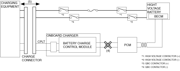
System operation at start of normal charging
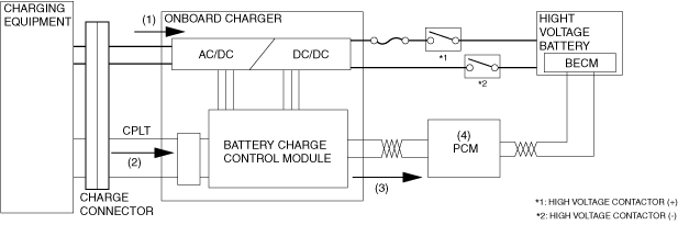
1. When the user connects the charge cable, the onboard charger detects that the charge cable has been connected and the battery charge control module is activated.
2. CLPT communication between the charging equipment and the vehicle starts.
3. When the battery charge control module determines that the charging equipment is normal via CPLT communication, the battery charge control module sends a charging request signal to the PCM via CAN communication.
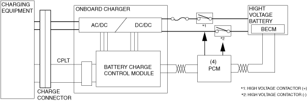
4. The PCM operates when a charging request signal is received from the battery charge control module.
a30zzn00002464
|
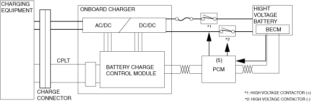
5. When the PCM turns on the high voltage contactors, the BECM operates, and it sends information about the high voltage battery to the PCM via CAN communication.
a30zzn00002465
|
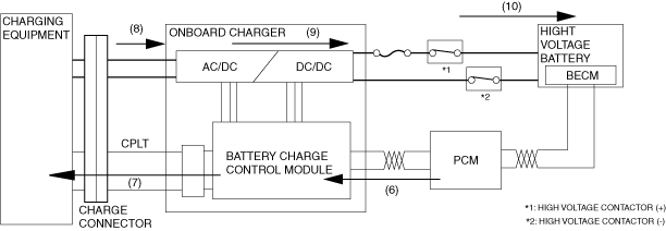
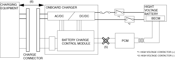
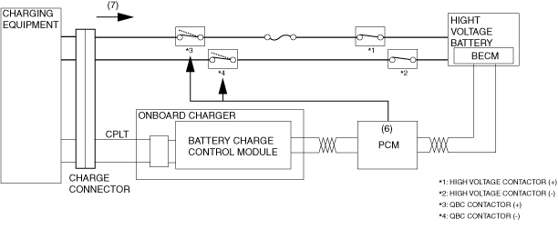
6. The PCM sends a charging request to the onboard charger.
7. The onboard charger requests power supply to the charging equipment based on the CPLT signal.
8. Power supply from the charging equipment starts.
9. When the alternating current supplied from the charging equipment is input to the onboard charger, the AC/DC converter in the onboard charger starts converting alternating current to direct current.
10. The current converted from alternating current to direct current is input to the high voltage battery through each fuse and contactor to charge the high voltage battery.
a30zzn00002466
|
System operation at end of normal charging
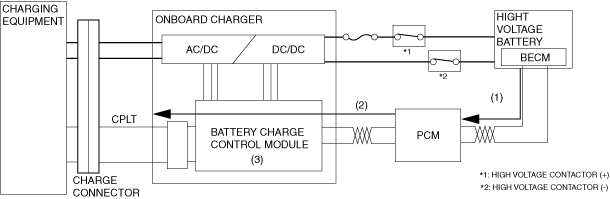
1. The BECM monitors the status of the high voltage battery and it sends the high voltage battery information to the PCM via CAN communication.
When the PCM determines that the high voltage battery is sufficiently charged, it sends a charging finished signal to each module via CAN communication.
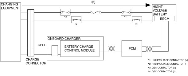
2. The PCM withdraws the charging request to the onboard charger and requests that the onboard charger stop the power conversion.
3. The onboard charger receives the request to stop the power conversion, gradually reduces the input current, and then stops the power conversion.
a30zzn00002467
|
4. The PCM turns off the high voltage contactors. Turning off the high voltage contactor turns off the BECM.
a30zzn00002468
|
5. The PCM and the battery charge control module are turned off by the PCM and the battery charge control module stopping CAN communication.
6. Charging also stops when the user unplugs the charging plug.
a30zzn00002469
|
System operation at start of quick charging
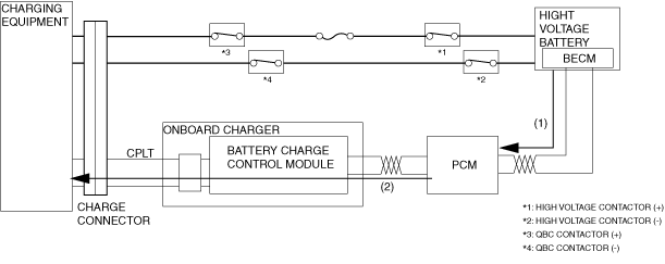
1. When the user connects the charge cable, the battery charge control module is operated by the detection of the charge cable as being connected.
2. CLPT communication between the charging equipment and the vehicle starts.
3. When the battery charge control module determines that the charging equipment is normal via CPLT communication, the battery charge control module sends a charging request signal to the PCM via CAN communication.
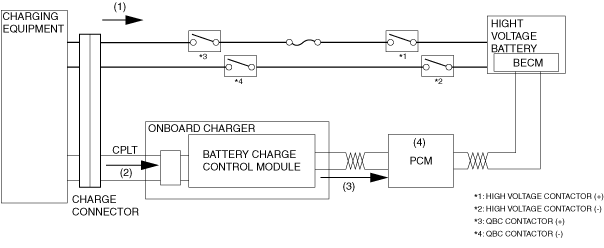
4. The PCM operates when a charging request signal is received from the battery charge control module.
a30zzn00002470
|
5. When the PCM turns on the high voltage contactors, the BECM operates, and it sends information about the high voltage battery to the PCM via CAN communication.
a30zzn00002471
|
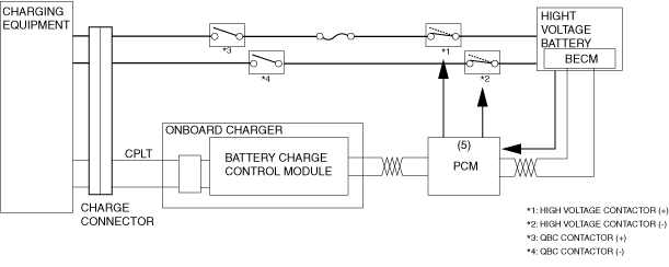
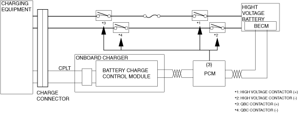
6. When the PCM turns on the QBC (Quick Battery Charge) contactor, the charging indication value is sent to the charging equipment via CPLT communication through the battery charge control module.
7. Power supply from the charging equipment starts.
a30zzn00002472
|
8. The direct current supplied from the charging equipment is input to the high voltage battery through each fuse and contactor to charge the high voltage battery.
The quick charging circuit contains a QBC (Quick Battery Charge) voltage sensor.
a30zzn00002473
|
System operation at end of quick charging
1. The BECM monitors the status of the high voltage battery and it sends the high voltage battery information to the PCM via CAN communication.
When the PCM determines that the high voltage battery is sufficiently charged, it sends a charging finished signal to each module via CAN communication.
2. When the charging finished signal from the PCM is input to the charging equipment via CPLT communication through the battery charge control module, the charging equipment stops supplying power.
a30zzn00002474
|
3. The PCM turns off the high voltage contactors, QBC (Quick Battery Charge) contactor, and the high voltage contactor. Turning off the high voltage contactor turns off the BECM.
a30zzn00002475
|
4. The PCM and the battery charge control module are turned off by the PCM and the battery charge control module stopping CAN communication.
5. Charging also stops when the user unplugs the charging plug.
a30zzn00002476
|