|
a30zzw00005120
BATTERY REMOVAL/INSTALLATION [SKYACTIV-G 2.0]
id0117009539h5
Replacement Part
|
Set bolt
Quantity: 2
Location of use: PCM cover
|
Operation After Replacing Battery
|
Step |
Action |
|---|---|
|
1
|
Close the all doors.
|
|
2
|
Switch the ignition ON (engine off).
|
|
3
|
If a warning message is displayed in the screen display, clear the screen using the INFO switch and then go to the next step.
|
|
4
|
Shift the selector lever to the N position
|
|
5
|
Perform the following work with the brake pedal depressed.
1. Depress the accelerator pedal for 5 s or more.
2. Verify that a warning message (master warning light) on the screen display flashes.
3. Depress and release the accelerator pedal 3 times.
4. Verify that a warning message (master warning light) on the screen display turn off.
|
|
6
|
Switch the ignition off and disconnect the negative battery terminal. (See NEGATIVE BATTERY TERMINAL DISCONNECTION/CONNECTION.)
|
|
7
|
Verifying battery condition initialization setting (i-stop setting). (See BATTERY CONDITION INITIALIZATION SETTING (i-stop SETTING).)
|
Battery Removal/Installation
1. Remove in the order indicated in the table.
2. Install in the reverse order of removal.
a30zzw00005120
|
|
1
|
Negative battery terminal
|
|
2
|
Positive battery terminal
|
|
3
|
Battery clamp
|
|
4
|
Battery
|
|
5
|
Battery box
|
|
6
|
Wiring harness
|
|
7
|
PCM connector
|
|
8
|
Bracket
|
|
9
|
Battery tray and PCM component
|
|
10
|
PCM
|
Battery and battery box removal note
Wiring harness disconnection note
1. Remove the following parts as a single unit: (See INTAKE-AIR SYSTEM REMOVAL/INSTALLATION [SKYACTIV-G 2.0].)
2. Disconnect the wiring harness.
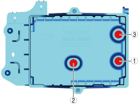
Battery tray and PCM component installation note
1. Tighten the battery tray installation bolts in the order shown in the figure.
am3zzw00030363
|
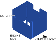
Battery box installation note
1. Install the battery box so that the side with the larger notch is pointed at the engine.
am3zzw00025286
|
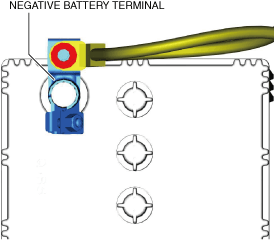
Positive battery terminal connection note
Negative battery terminal connection note
1. Connect the negative battery terminal so that the wiring harness does not block the upper part of the battery filler cap.
a30zzw00005121
|