DRIVE-BY-WIRE CONTROL [SKYACTIV-G 2.0]
id0140f4188400
Outline
• Calculates the optimum target throttle valve opening angle and controls the throttle valve actuator which allows the driver to drive the vehicle at will.
• The drive-by-wire control is composed of the idle air control, accelerator control, traction control, excess engine speed control, overspeed control, electric variable valve timing cooperation control, brake override system, engine oil temperature control.
Control Table
|
Control name
|
Control outline
|
|
Idle air control
|
• While idling, the throttle valve opening is controlled so that the idle speed is at the target idle speed.
|
|
Accelerator control
|
• The throttle valve opening angle is controlled according to the amount the accelerator pedal is depressed. In addition, there is a fully closed learning function for learning deterioration over time and constant correction of the optimum throttle opening angle.
|
|
Traction control
|
• The throttle valve opening angle is controlled by the torque reduction request signal from the electronically controlled brake unit.
|
|
Excess engine speed control
|
• If the engine reaches a high engine speed, the throttle valve opening angle is controlled to protect the engine.
|
|
Overspeed control
|
• If the vehicle reaches a high speed, the throttle valve is closed to keep the vehicle speed below the speed limit.
|
|
Electric variable valve timing cooperation control
|
• Pumping loss is reduced by controlling the throttle valve timing opening angle according to the phase of the intake valve timing.
|
|
Vehicle speed restriction control
|
• If a malfunction occurs where power cannot be supplied from the power supply part while driving, vehicle speed restriction is performed to urge the driver to stop the vehicle and ultimately the Auto P function is activated. (See AutoP FUNCTION.) |
|
Brake override system
|
• If the brake pedal is depressed with the accelerator pedal depressed, the vehicle can be stopped safely by closing the throttle valve. As a result, the brake operation takes priority over the accelerator pedal operation.
|
|
Engine oil temperature control
|
• If the PCM determines that the engine oil temperature is too high, the throttle valve opening angle is decreased and the engine speed is reduced.
|
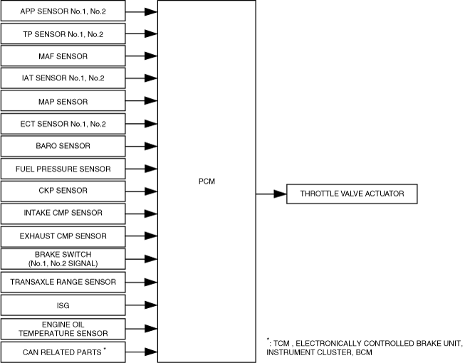
Block Diagram
Operation
Idle air control
-
• The idle speed control controls the throttle valve opening angle according to the engine torque to achieve the target idle speed.
• The PCM drives the throttle valve actuator so that the actual idle speed approaches the target idle speed.
-
Target idle speed calculation
-
• Calculates the target idle speed according to the purpose of use such as the basic idle speed and fast idle up*.
-
*: The catalytic converter is activated quickly after cold-engine starts.
-
Engine torque calculation to achieve target idle speed
-
• The engine torque is controlled in consideration of the following factors to realize the target idle speed.
-
― Feedback: The torque difference is added so that the actual idle speed approaches the target idle speed.
― Engine mechanical resistance: Changes according to the engine coolant temperature.
― Pumping loss: Changes based on the valve timing and intake air pressure.
― External electric load: Changes depending on the A/C ON/OFF, generator power generation amount.
― D position torque: Adds load torque from torque converter.
Accelerator control
-
• The accelerator control controls the throttle valve opening angle according to the accelerator pedal depression amount.
• The PCM controls the throttle valve actuator so that the actual throttle valve opening angle approaches the final target throttle valve opening angle.
• The target throttle valve opening angle is determined by the transmission gear position, accelerator pedal depression amount, and vehicle speed.
• Because deviation in the throttle valve opening angle due to deterioration over time is corrected when the ignition is switched off, the PCM operates the fully-closed learning function. The fully-closed learning function is a function for learning the fully-closed throttle valve position.
Traction control
-
• The throttle valve opening angle is controlled by the torque reduction request signal from the DSC HU/CM.
Excess engine speed control
-
• If the engine reaches high-speed rotation*, the throttle valve is closed to maintain the engine speed at the limit speed or less to protect the engine. *Value fluctuates depending on various conditions.
Overspeed control
-
• If the vehicle reaches a high speed, the throttle valve is closed to keep the vehicle speed below the speed limit.
Electric variable valve timing cooperation control
-
• The PCM calculates the target throttle valve opening angle according to change in the phase of the intake valve timing due to electrical variable valve timing control.
Engine oil temperature control
-
• If any of the following conditions is met, the engine speed is restricted to protect the engine (determination of engine oil temperature is too high). DTC P117A:00 is recorded simultaneously.
-
― While in 5th gear or lower, the estimated engine oil temperature is higher than 140 °C {284 °F}.
― While in 5th gear or lower, an engine coolant temperature of 88.5 °C {191 °F} or more and an engine speed of 6,100 rpm continues for 6 min.
Vehicle speed restriction control
-
• If any of the following conditions is met, the PCM limits the maximum vehicle speed in 2 steps (180 km/h to 100 km/h and 100 km/h to 20 km/h).*1 If the vehicle cannot supply power, the Auto P function is activated to shift the shift lever to the P position.
-
― Charging system warning light turns on and battery voltage decreases
― Low fuel warning light flashes and Mazda M Hybrid battery output is restricted
*1 :A message is displayed on the multi-information display and a shift lever position warning sound is activated while the vehicle speed is restricted.
Brake override system
-
Brake override system operation conditions
-
• It gives priority to the brake operation if a malfunction occurs with the accelerator pedal such as if the accelerator pedal is depressed and does not return. The throttle valve is closed if the brake pedal is depressed while the accelerator pedal is in a depressed condition until the vehicle is safely decelerated and comes to a complete stop.
|
Operation start conditions
|
• If any of the following conditions is met and the accelerator pedal and the brake pedal are depressed*1, the PCM adjusts the throttle valve opening angle so that the engine speed is the specification*2.
While driving vehicle
-
― Accelerator pedal opening angle: 5% or more from full-close
― Vehicle speed: 10 km/h {6.2 mph} or more
― Engine speed: 875 rpm or more
While vehicle stopped
-
― Accelerator pedal opening angle: 5% or more from full-close
― Selector lever position: N position
― Engine speed: 875 rpm or more
|
|
Operation complete conditions
|
• If the following conditions are met while operating the brake override system, the PCM stops the operation of the brake override system and controls the throttle valve opening angle in accordance with the accelerator pedal opening angle.
-
― Accelerator pedal not depressed
― Brake pedal not depressed
-
Note
-
• The brake override system operation stops by switching the ignition off.
|
*1 :The control may not operate depending on the brake pedal depression amount.
*2 :Specification is 1,200 rpm while vehicle is stopped and 1,100 rpm while vehicle is driven.
-
Prevention of brake override system unnecessary operation
-
• If a servicing procedure requiring the brake pedal and the accelerator pedal to be depressed simultaneously is performed, unnecessary operation of the brake override system can be prevented, if necessary.
|
Cancel conditions
|
• If the releasing procedure is implemented with the following conditions met within 30 s after switching the ignition ON (KOEO), the brake override system does not operate until the recovery condition is met.
-
― Selector lever position: N position
― Vehicle speed: 0 km/h {0 mph}
Releasing procedure
-
1. Depress the brake pedal for 10 s with the accelerator pedal released.
2. Repeatedly depress and release the accelerator pedal fully three times with the brake pedal depressed.
3. Release the brake pedal.
|
|
Recovery condition
|
• The cancel conditions are reset when the ignition is switched off while the brake override system is canceled. As a result, the brake override system can operate.
|
-
Master warning light illumination request
-
• If any of the following conditions is met, the PCM sends the master warning light illumination request signal to the instrument cluster. The master warning light illuminates to alert the driver that there is a malfunction in the brake system.
-
― Brake switch (No.1 signal) has a malfunction
― Brake switch (No.2 signal) has a malfunction
-
Master warning light flash request
-
• If the cancel condition for preventing unnecessary operation of the brake override system is implemented, the PCM sends a brake override system cancel execution signal to the instrument cluster.
• The instrument cluster flashes the master warning light based on the signal from the PCM.