WARNING/INDICATION/ALARM [SKYACTIV-G 2.0]
id0140f4267800
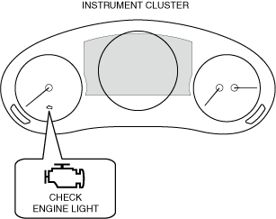
CHECK ENGINE LIGHT
Purpose
-
• If a malfunction occurs in the engine control system, the light illuminates to warn the driver of the malfunction.
Function
-
• The check engine light illuminates when a malfunction occurs in the engine control system, and it illuminates at the same time a DTC is recorded in the PCM.
• The PCM sends a check engine light illumination request to the instrument cluster via CAN communication.
Structure/Construction
-
• The check engine light is equipped in the instrument cluster.
• A warning message in the center display is displayed when the check engine light is illuminated or flashes. For the message content and verification method, refer to the [CENTER DISPLAY] in the workshop manual.
Operation
-
• The illumination conditions for the check engine light are determined by the number of drive cycles set for each DTC. For details on the drive cycle, refer to “workshop manual”.
-
― For DTCs with one drive cycle, if a malfunction is detected in the first drive cycle, the check engine light illuminates.
― For DTCs with two drive cycles, if each malfunction is detected in the first and second drive cycles, the check engine light illuminates. However, if the same malfunction as the DTC stored in the PCM is detected, the check engine light illuminates in the first drive cycle even if the DTC is two drive cycles.
― If the PCM detects that the engine control system is continuously normal for three drive cycles, the illuminated check engine light turns off.
ENGINE OIL WARNING INDICATION/ENGINE OIL WARNING LIGHT
Purpose
-
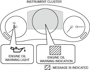
• The engine oil warning indication/engine oil warning light warns the driver that the engine oil pressure is insufficient.
Function
-
• If the engine oil pressure is low, the PCM sends an engine oil warning indication/engine oil warning light illumination request signal to the instrument cluster.
• When the instrument cluster receives the engine oil warning indication/engine oil warning light illumination request signal sent from the PCM as a CAN signal, it turns the engine oil warning indication/engine oil warning light on.
Construction
-
• The engine oil warning indication/engine oil warning light is equipped in the instrument cluster.
• A warning message is displayed in the multi-information display as the same time the engine oil warning indication is displayed. For the message content and verification method, refer to [MULTI-INFORMATION DISPLAY]. (See
MULTI-INFORMATION DISPLAY.)
• A warning message in the center display is displayed when the engine oil warning indication/engine oil warning light is illuminated. For the message content and verification method, refer to the [CENTER DISPLAY] in the workshop manual.
Operation
-
Engine oil warning indication
-
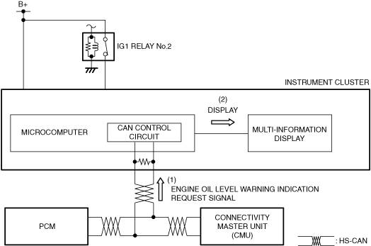
1. When the ignition is switched ON (engine off or on), the instrument cluster receives (1) an engine oil warning indication request signal from the PCM or the CMU via CAN communication.
2. The instrument cluster displays (2) the engine oil warning indication in the multi-information display.
-
Engine oil warning light
-
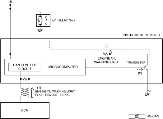
1. The instrument cluster receives (1) the engine oil warning light request signal from the PCM.
2. The instrument cluster microcomputer turns the transistor on (2) based on the engine oil warning light request signal.
3. When the transistor turns on, a ground circuit with the engine oil warning light is established and the engine oil warning light illuminates (3).
ENGINE OIL LEVEL WARNING INDICATION/ENGINE OIL LEVEL WARNING LIGHT
Purpose
-
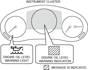
• The engine oil level warning indication/warning light warns the driver that the engine oil level is at the MIN position on the oil level gauge, or the engine oil level sensor is malfunctioning.
Function
-
• The PCM sends an engine oil level warning light illumination/engine oil warning indication request signal to the instrument cluster.
• When the instrument cluster receives an engine oil level warning light illumination request signal/engine oil level warning indication request signal sent from the PCM via CAN communication, it turns the engine oil level warning light on or displays the engine oil level warning indication.
Construction
-
• The engine oil level warning indication is displayed in the multi-information display
• The engine oil level warning light is built into the instrument cluster.
• A warning message is displayed in the center display as the same time the engine oil level warning light is turned on/engine oil level warning indication is displayed. For the message content and verification method, refer to [CENTER DISPLAY] in the workshop manual.
Operation
-
• The condition related to the engine oil level warning light is as follows.
-
― PCM determines that engine oil level is in MIN position on oil level gauge
• The condition related to the engine oil level warning indication is as follows.
-
― PCM determines that engine oil level sensor is malfunctioning
-
Engine oil level warning indication
-
1. When the ignition is switched ON (engine off or on), the instrument cluster receives (1) an engine oil level warning indication request signal from the PCM via CAN communication.
2. The instrument cluster displays (2) the engine oil level warning indication in the multi-information display.
-
Engine oil level warning light
-
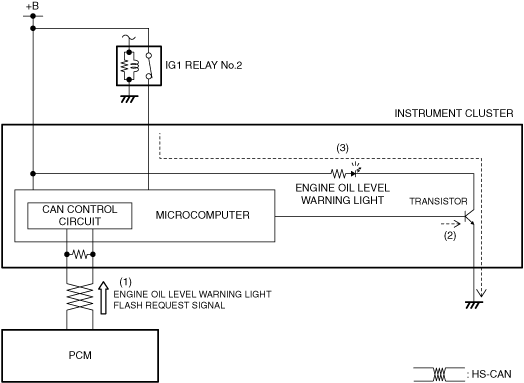
1. When the ignition is switched ON (engine off or on), the instrument cluster receives (1) an engine oil level warning light illumination request signal from the PCM via CAN communication.
2. The instrument cluster turns the transistor on (2) based on the engine oil level warning light illumination request signal.
3. When the transistor turns on, a ground circuit with the engine oil level warning light is established and the engine oil level warning light turns on (3).
WRENCH INDICATION/WRENCH INDICATOR LIGHT
Purpose
-
• The wrench indication/wrench indicator light notifies the driver that the maintenance period previously set by the driver is approaching, or that the PCM has determined engine oil deterioration.
Function
-
• When a maintenance period previously set by the driver is approaching, or if the PCM determines engine oil deterioration, the PCM sends a wrench indication request signal/wrench indicator light illumination request signal to the instrument cluster.
• When the instrument cluster receives a wrench indication request signal/wrench indicator light illumination request signal sent from the connectivity master unit (CMU) or the PCM via CAN communication, it turns the wrench indicator light on or displays the wrench indication.
Construction
-
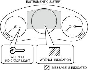
• The wrench indication/wrench indicator light is built into the instrument cluster.
• A warning message is displayed in the multi-information display as the same time the wrench indicator light is turned on/wrench indication is displayed. For the message content and verification method, refer to [MULTI-INFORMATION DISPLAY]. (See
MULTI-INFORMATION DISPLAY.)
• A warning message is displayed in the center display as the same time the wrench indicator light is turned on/wrench indication is displayed. For the message content and verification method, refer to [CENTER DISPLAY] in the workshop manual.
Operation
-
• The wrench warning indicator light illumination conditions are as follows:
-
― When the preset maintenance period is approaching
― PCM determines engine oil replacement period reached.
-
Wrench indication
-
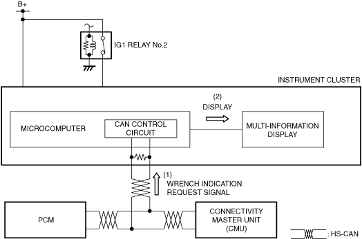
1. When the ignition is switched ON (engine off or on), the instrument cluster receives (1) a wrench indication request signal from the PCM or the CMU via CAN communication.
2. The instrument cluster displays (2) the wrench indication in the multi-information display.
-
Wrench indicator light
-
1. When the ignition is switched ON (engine off or on), the instrument cluster receives (1) a wrench indicator light illumination request signal from the PCM or the CMU via CAN communication.
2. The instrument cluster turns the transistor on (2) based on the wrench indicator light illumination request signal.
3. When the transistor turns on, a ground circuit with the wrench indicator light is established and the wrench indicator light turns on (3).
i-stop WARNING LIGHT (AMBER)
Purpose, Function
-
• If the i-stop control inhibits the operation, the i-stop warning light (amber) flashes/illuminates to inform the driver that the i-stop control inhibits the operation.
Construction
-
• The i-stop warning light (amber) is equipped in the instrument cluster.
• A warning message in the center display is displayed when the i-stop warning light (amber) is illuminated or flashes. For the message content and verification method, refer to the [CENTER DISPLAY] in the workshop manual.
Operation
-
• The flashing/illumination conditions of the i-stop warning light (amber) are as follows:
i-stop warning light (amber) flashing condition
-
― Any of the following DTCs are stored:
PCM DTC
-
• For details on DTCs, refer to the workshop manual.
TCM DTC
-
• For details on DTCs, refer to the workshop manual.
Electronically controlled brake unit DTC
-
• For details on DTCs, refer to the workshop manual.
EPS control module DTC
-
• For details on DTCs, refer to the workshop manual.
i-stop warning light (amber) illumination condition
-
― Any one of the following conditions is met:
-
• Ignition switched ON (check of i-stop control system)
• Engine stalls due to driver's operation while engine is stopped by i-stop control
• Communication error to PCM and instrument cluster
-
• The PCM sends an i-stop warning light (amber) flashing/illumination request to the instrument cluster via CAN communication.
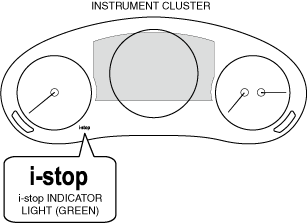
i-stop INDICATOR LIGHT (GREEN)
Purpose, Function
-
• The i-stop indicator light (green) notifies the driver that the engine is stopped by i-stop control.
Construction
-
• The i-stop indicator light (green) is built into the instrument cluster.
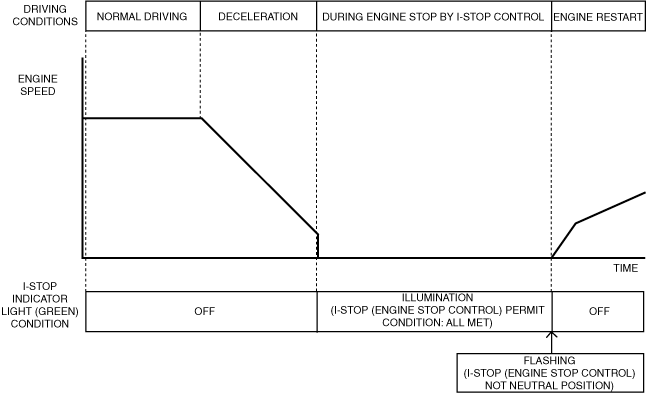
Operation
-
• The illumination/flashing conditions of the i-stop indicator light (green) differ depending on the i-stop (engine-stop control) permit condition.
• The illumination/flashing conditions of the i-stop indicator light (green) are as follows:
|
i-stop (engine-stop control) permit condition item
|
ATX
|
|
Cabin temperature
|
Difference between target temperature in cabin and temperature in cabin is within a certain value (A/C cabin temperature control is performed)
|
|
A/C temperature
|
Setting other than MAX/MIN
|
|
Cold condition
|
Ambient temperature is 4 °C {39 °F} or less and evaporator temperature is 12 °C {54 °F} or less
|
|
Ambient temperature
|
-10―50 °C {14―122 °F}
|
|
i-stop OFF switch
|
OFF
|
|
Vehicle speed history
|
3 km/h {2 mph} or more
|
|
Mazda M Hybrid battery voltage
|
20 V or more
|
|
Mazda M Hybrid battery condition
|
30 % or more
|
|
Mazda M Hybrid battery temperature
|
59 °C {138 °F}
|
|
Door (driver side)
|
Closed
|
|
Hood
|
Closed *1
|
|
Seat belt (driver side)
|
Fastened*2
|
|
System condition
|
i-stop related module is normal
|
|
Steering angle sensor initialization setting
|
Completed
|
|
Engine coolant temperature
|
30—110 °C {86—230 °F}
|
|
Intake air temperature
|
100°C {212 °F} or less
|
|
TFT
|
20―117 °C {68―242 °F}
|
|
Altitude
|
2,000 m or less
|
|
Vehicle speed
|
20 km/h {12 mph}
|
|
Vehicle conditions
|
Vehicle stopped in D position*3
|
|
Brake pedal
|
Brake pedal is depressed while in D position
However, no brake pedal conditions during Mazda Radar Cruise Control with Stop & Go function (MRCC with Stop & Go function) and Cruising & Traffic Support (CTS) operation*4
|
|
Accelerator pedal
|
Released
|
|
Steering speed
|
15 deg/sec or less
|
|
Steering angle
|
Within 65° of center to left and right
(After EPS control module learns center value)
|
|
Steering torque
|
1.1 N·m {11 kgf·cm, 9.7 in·lbf} or less
|
|
Door (front, rear)
|
Closed
|
|
Liftgate
|
Closed
|
|
Vehicle inclination angle
|
Inclination is within ±7° with shift positioned in D/R or N/P (LON_ACCL_C: within ±0.104 G)
|
|
Gear position
|
Not in 2nd gear fixed mode
|
*1 :If the engine is started with the bonnet open, i-stop is inhibited until the engine is stopped.
*2 :If the seat belt is unfastened while the vehicle is stopped, i-stop is inhibited until a vehicle speed record is input once.
*3 :After the vehicle is stopped, the engine stops if the gear is shifted to N position. In addition, if the gear is shifted to P position after the vehicle is stopped in D position, the engine stop condition by the i-stop control is maintained.
*4 :During Mazda Radar Cruise Control with Stop & Go function (MRCC with Stop & Go function) and Cruising & Traffic Support (CTS) operation, the engine is stopped by i-stop control without having to depress the brake pedal.
-
• The PCM sends an i-stop indicator light (green) illumination/flashing request to the instrument cluster via CAN communication.
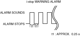
i-stop WARNING ALARM
Purpose
-
• The i-stop warning alarm alerts the driver that the driver-side door is open or the engine stalls while the engine is stopped by i-stop control.
Function
-
• When the instrument cluster receives the i-stop warning alarm request signal sent from the PCM via the CAN signal, the i-stop warning alarm sounds.
• The i-stop warning alarm sound pattern is as shown in the figure.
Construction
-
• The i-stop warning alarm sounds using the buzzer built into the instrument cluster.
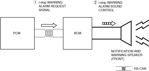
Operation
-
1. When the BCM receives (1) a i-stop warning alarm signal via CAN communication from the Instrument cluster, the BCM sounds the notification and warning speaker (2).