am3zzw00034781
|
-
• Standard
-
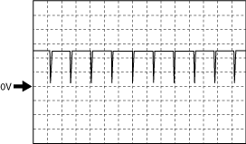
4.5 V or more (Maximum value of wave pattern)0.8 V or less (Minimum value of wave pattern)
-
CRANKSHAFT POSITION (CKP) SENSOR INSPECTION [SKYACTIV-G 2.0]
id0140f4800500
Visual Inspection
1. Disconnect the negative battery terminal. (See NEGATIVE BATTERY TERMINAL DISCONNECTION/CONNECTION.)
2. Remove the CKP sensor. (See CRANKSHAFT POSITION (CKP) SENSOR REMOVAL/INSTALLATION [SKYACTIV-G 2.0].)
3. Verify that there are no metal shavings on the sensor.
Voltage Inspection
1. Idle the engine.
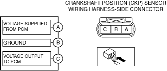
2. Measure the output voltage wave pattern between CKP sensor terminals C and B using an oscilloscope.
am3zzw00034781
|
Wave pattern (reference)
adejjw00007912
|