 |
a30zzw00005651
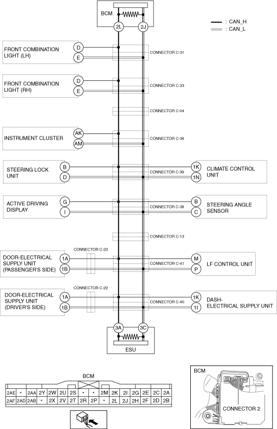
DETERMINING SHORT TO GROUND LOCATION (CAN-BUS No.3)
id100200002600
System Wiring Diagram
a30zzw00005651
|
Determination Procedure
|
Step |
Inspection |
Action |
|
|---|---|---|---|
|
1
|
INSPECT FOR SHORT TO GROUND BETWEEN BODY CONTROL MODULE (BCM) AND CONNECTOR C-31
• Switch the ignition off.
• Disconnect the negative battery terminal.
• Disconnect the connector C-31.
• Inspect for continuity at the following terminals:
• Is there continuity?
|
Yes
|
Go to the next step.
|
|
No
|
Go to Step 3.
|
||
|
2
|
INSPECT CAN LINE IN BODY CONTROL MODULE (BCM) FOR SHORT TO GROUND
• Disconnect the connector 2 which has body control module (BCM) terminals 2L and 2J.
• Inspect for continuity at the following terminals:
• Is there continuity?
|
Yes
|
Repair or replace the wiring harness between the body control module (BCM) and connector C-31 because the wiring harness is shorted to ground.
|
|
No
|
Replace the body control module (BCM) because there is a short to ground in the body control module (BCM).
|
||
|
3
|
INSPECT FOR SHORT TO GROUND BETWEEN FRONT COMBINATION LIGHT (LH) AND CONNECTOR C-31
• Inspect for continuity at the following terminals:
• Is there continuity?
|
Yes
|
Go to the next step.
|
|
No
|
Go to Step 5.
|
||
|
4
|
INSPECT CAN LINE IN FRONT COMBINATION LIGHT (LH) FOR SHORT TO GROUND
• Disconnect the front combination light (LH) connector.
• Inspect for continuity at the following terminals:
• Is there continuity?
|
Yes
|
Repair or replace the wiring harness between the front combination light (LH) and connector C-31 because the wiring harness is shorted to ground.
|
|
No
|
Replace the front combination light (LH) because there is a short to ground in the front combination light (LH).
|
||
|
5
|
INSPECT FOR SHORT TO GROUND BETWEEN CONNECTOR C-31 AND CONNECTOR C-33
• Disconnect the connector C-33.
• Connect the connector C-31.
• Inspect for continuity at the following terminals:
• Is there continuity?
|
Yes
|
Repair or replace the wiring harness between the connector C-31 and connector C-33 because the wiring harness is shorted to ground.
|
|
No
|
Go to the next step.
|
||
|
6
|
INSPECT FOR SHORT TO GROUND BETWEEN FRONT COMBINATION LIGHT (RH) AND CONNECTOR C-33
• Inspect for continuity at the following terminals:
• Is there continuity?
|
Yes
|
Go to the next step.
|
|
No
|
Go to Step 8.
|
||
|
7
|
INSPECT CAN LINE IN FRONT COMBINATION LIGHT (RH) FOR SHORT TO GROUND
• Disconnect the front combination light (RH) connector.
• Inspect for continuity at the following terminals:
• Is there continuity?
|
Yes
|
Repair or replace the wiring harness between the front combination light (RH) and connector C-33 because the wiring harness is shorted to ground.
|
|
No
|
Replace the front combination light (RH) because there is a short to ground in the front combination light (RH).
|
||
|
8
|
INSPECT FOR SHORT TO GROUND BETWEEN CONNECTOR C-04 AND CONNECTOR C-33
• Disconnect the connector C-04.
• Connect the connector C-33.
• Inspect for continuity at the following terminals:
• Is there continuity?
|
Yes
|
Repair or replace the wiring harness between the connector C-04 and connector C-33 because the wiring harness is shorted to ground.
|
|
No
|
Go to the next step.
|
||
|
9
|
INSPECT FOR SHORT TO GROUND BETWEEN CONNECTOR C-36 AND CONNECTOR C-04
• Disconnect the connector C-36.
• Connect the connector C-04.
• Inspect for continuity at the following terminals:
• Is there continuity?
|
Yes
|
Repair or replace the wiring harness between the connector C-36 and connector C-04 because the wiring harness is shorted to ground.
|
|
No
|
Go to the next step.
|
||
|
10
|
INSPECT FOR SHORT TO GROUND BETWEEN INSTRUMENT CLUSTER AND CONNECTOR C-36
• Inspect for continuity at the following terminals:
• Is there continuity?
|
Yes
|
Go to the next step.
|
|
No
|
Go to Step 12.
|
||
|
11
|
INSPECT CAN LINE IN INSTRUMENT CLUSTER FOR SHORT TO GROUND
• Disconnect the instrument cluster connector.
• Inspect for continuity at the following terminals:
• Is there continuity?
|
Yes
|
Repair or replace the wiring harness between the instrument cluster and connector C-36 because the wiring harness is shorted to ground.
|
|
No
|
Replace the instrument cluster because there is a short to ground in the instrument cluster.
|
||
|
12
|
INSPECT FOR SHORT TO GROUND BETWEEN CONNECTOR C-39 AND CONNECTOR C-36
• Disconnect the connector C-39.
• Connect the connector C-36.
• Inspect for continuity at the following terminals:
• Is there continuity?
|
Yes
|
Repair or replace the wiring harness between the connector C-36 and connector C-39 because the wiring harness is shorted to ground.
|
|
No
|
Go to the next step.
|
||
|
13
|
INSPECT FOR SHORT TO GROUND BETWEEN STEERING LOCK UNIT AND CONNECTOR C-39
• Inspect for continuity at the following terminals:
• Is there continuity?
|
Yes
|
Go to the next step.
|
|
No
|
Go to Step 15.
|
||
|
14
|
INSPECT CAN LINE IN STEERING LOCK UNIT FOR SHORT TO GROUND
• Disconnect the steering lock unit connector.
• Inspect for continuity at the following terminals:
• Is there continuity?
|
Yes
|
Repair or replace the wiring harness between the steering lock unit and connector C-39 because the wiring harness is shorted to ground.
|
|
No
|
Replace the steering lock unit because there is a short to ground in the steering lock unit.
|
||
|
15
|
INSPECT FOR SHORT TO GROUND BETWEEN CLIMATE CONTROL UNIT AND CONNECTOR C-39
• Inspect for continuity at the following terminals:
• Is there continuity?
|
Yes
|
Go to the next step.
|
|
No
|
Go to Step 17.
|
||
|
16
|
INSPECT CAN LINE IN CLIMATE CONTROL UNIT FOR SHORT TO GROUND
• Disconnect the climate control unit connector.
• Inspect for continuity at the following terminals:
• Is there continuity?
|
Yes
|
Repair or replace the wiring harness between the climate control unit and connector C-39 because the wiring harness is shorted to ground.
|
|
No
|
Replace the climate control unit because there is a short to ground in the climate control unit.
|
||
|
17
|
INSPECT FOR SHORT TO GROUND BETWEEN CONNECTOR C-39 AND CONNECTOR C-38
• Disconnect the connector C-38.
• Connect the connector C-39.
• Inspect for continuity at the following terminals:
• Is there continuity?
|
Yes
|
Repair or replace the wiring harness between the connector C-38 and connector C-39 because the wiring harness is shorted to ground.
|
|
No
|
Go to the next step.
|
||
|
18
|
INSPECT FOR SHORT TO GROUND BETWEEN ACTIVE DRIVING DISPLAY AND CONNECTOR C-38
• Inspect for continuity at the following terminals:
• Is there continuity?
|
Yes
|
Go to the next step.
|
|
No
|
Go to Step 20.
|
||
|
19
|
INSPECT CAN LINE IN ACTIVE DRIVING DISPLAY FOR SHORT TO GROUND
• Disconnect the active driving display connector.
• Inspect for continuity at the following terminals:
• Is there continuity?
|
Yes
|
Repair or replace the wiring harness between the active driving display and connector C-38 because the wiring harness is shorted to ground.
|
|
No
|
Replace the active driving display because there is a short to ground in the active driving display.
|
||
|
20
|
INSPECT FOR SHORT TO GROUND BETWEEN STEERING ANGLE SENSOR AND CONNECTOR C-38
• Inspect for continuity at the following terminals:
• Is there continuity?
|
Yes
|
Go to the next step.
|
|
No
|
Go to Step 22.
|
||
|
21
|
INSPECT CAN LINE IN STEERING ANGLE SENSOR FOR SHORT TO GROUND
• Disconnect the steering angle sensor connector.
• Inspect for continuity at the following terminals:
• Is there continuity?
|
Yes
|
Repair or replace the wiring harness between the steering angle sensor and connector C-38 because the wiring harness is shorted to ground.
|
|
No
|
Replace the steering angle sensor because there is a short to ground in the steering angle sensor.
|
||
|
22
|
INSPECT FOR SHORT TO GROUND BETWEEN CONNECTOR C-38 AND CONNECTOR C-13
• Disconnect the connector C-13.
• Connect the connector C-38.
• Inspect for continuity at the following terminals:
• Is there continuity?
|
Yes
|
Repair or replace the wiring harness between the connector C-38 and connector C-13 because the wiring harness is shorted to ground.
|
|
No
|
Go to the next step.
|
||
|
23
|
INSPECT FOR SHORT TO GROUND BETWEEN CONNECTOR C-41 AND CONNECTOR C-13
• Disconnect the connector C-41.
• Connect the connector C-13.
• Inspect for continuity at the following terminals:
• Is there continuity?
|
Yes
|
Repair or replace the wiring harness between the connector C-41 and connector C-13 because the wiring harness is shorted to ground.
|
|
No
|
Go to the next step.
|
||
|
24
|
INSPECT FOR SHORT TO GROUND BETWEEN DOOR-ELECTRICAL SUPPLY UNIT (PASSENGER'S SIDE) AND CONNECTOR C-41
• Inspect for continuity at the following terminals:
• Is there continuity?
|
Yes
|
Go to the next step.
|
|
No
|
Go to Step 27.
|
||
|
25
|
INSPECT FOR SHORT TO GROUND BETWEEN DOOR-ELECTRICAL SUPPLY UNIT (PASSENGER'S SIDE) AND CONNECTOR C-23
• Disconnect the connector C-23.
• Inspect for continuity at the following terminals:
• Is there continuity?
|
Yes
|
Go to the next step.
|
|
No
|
Repair or replace the wiring harness between the connector C-41 and connector C-23 because the wiring harness is shorted to ground.
|
||
|
26
|
INSPECT CAN LINE IN DOOR-ELECTRICAL SUPPLY UNIT (PASSENGER'S SIDE) FOR SHORT TO GROUND
• Disconnect the door-electrical supply unit (passenger's side) connector.
• Inspect for continuity at the following terminals:
• Is there continuity?
|
Yes
|
Repair or replace the wiring harness between the door-electrical supply unit (passenger's side) and connector C-23 because the wiring harness is shorted to ground.
|
|
No
|
Replace the door-electrical supply unit (passenger's side) because there is a short to ground in the door-electrical supply unit (passenger's side).
|
||
|
27
|
INSPECT FOR SHORT TO GROUND BETWEEN LF CONTROL UNIT AND CONNECTOR C-41
• Inspect for continuity at the following terminals:
• Is there continuity?
|
Yes
|
Go to the next step.
|
|
No
|
Go to Step 29.
|
||
|
28
|
INSPECT CAN LINE IN LF CONTROL UNIT FOR SHORT TO GROUND
• Disconnect the LF control unit connector.
• Inspect for continuity at the following terminals:
• Is there continuity?
|
Yes
|
Repair or replace the wiring harness between the LF control unit and connector C-41 because the wiring harness is shorted to ground.
|
|
No
|
Replace the LF control unit because there is a short to ground in the LF control unit.
|
||
|
29
|
INSPECT FOR SHORT TO GROUND BETWEEN CONNECTOR C-41 AND CONNECTOR C-40
• Disconnect the connector C-40.
• Connect the connector C-41.
• Inspect for continuity at the following terminals:
• Is there continuity?
|
Yes
|
Repair or replace the wiring harness between the connector C-40 and connector C-41 because the wiring harness is shorted to ground.
|
|
No
|
Go to the next step.
|
||
|
30
|
INSPECT FOR SHORT TO GROUND BETWEEN DOOR-ELECTRICAL SUPPLY UNIT (DRIVER'S SIDE) AND CONNECTOR C-40
• Inspect for continuity at the following terminals:
• Is there continuity?
|
Yes
|
Go to the next step.
|
|
No
|
Go to Step 33.
|
||
|
31
|
INSPECT FOR SHORT TO GROUND BETWEEN DOOR-ELECTRICAL SUPPLY UNIT (DRIVER'S SIDE) AND CONNECTOR C-22
• Disconnect the connector C-22.
• Inspect for continuity at the following terminals:
• Is there continuity?
|
Yes
|
Go to the next step.
|
|
No
|
Repair or replace the wiring harness between the connector C-40 and connector C-22 because the wiring harness is shorted to ground.
|
||
|
32
|
INSPECT CAN LINE IN DOOR-ELECTRICAL SUPPLY UNIT (DRIVER'S SIDE) FOR SHORT TO GROUND
• Disconnect the door-electrical supply unit (driver's side) connector.
• Inspect for continuity at the following terminals:
• Is there continuity?
|
Yes
|
Repair or replace the wiring harness between the door-electrical supply unit (driver's side) and connector C-22 because the wiring harness is shorted to ground.
|
|
No
|
Replace the door-electrical supply unit (driver's side) because there is a short to ground in the door-electrical supply unit (driver's side).
|
||
|
33
|
INSPECT FOR SHORT TO GROUND BETWEEN DASH-ELECTRICAL SUPPLY UNIT AND CONNECTOR C-40
• Inspect for continuity at the following terminals:
• Is there continuity?
|
Yes
|
Go to the next step.
|
|
No
|
Go to Step 35.
|
||
|
34
|
INSPECT CAN LINE IN DASH-ELECTRICAL SUPPLY UNIT FOR SHORT TO GROUND
• Disconnect the dash-electrical supply unit connector.
• Inspect for continuity at the following terminals:
• Is there continuity?
|
Yes
|
Repair or replace the wiring harness between the dash-electrical supply unit and connector C-40 because the wiring harness is shorted to ground.
|
|
No
|
Replace the dash-electrical supply unit because there is a short to ground in the dash-electrical supply unit.
|
||
|
35
|
INSPECT CAN LINE IN ELECTRICAL SUPPLY UNIT (ESU) FOR SHORT TO GROUND
• Disconnect the electrical supply unit (ESU) connector.
• Inspect for continuity at the following terminals:
• Is there continuity?
|
Yes
|
Repair or replace the wiring harness between the electrical supply unit (ESU) and connector C-40 because the wiring harness is shorted to ground.
|
|
No
|
Replace the electrical supply unit (ESU) because there is a short to ground in the electrical supply unit (ESU).
|
||