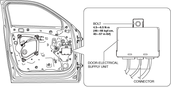
DOOR-ELECTRICAL SUPPLY UNIT REMOVAL/INSTALLATION
id094000700500
1. Disconnect the negative battery terminal. (See NEGATIVE BATTERY TERMINAL DISCONNECTION/CONNECTION.)
2. Remove the following parts:
- (1) Inner garnish (See INNER GARNISH REMOVAL/INSTALLATION.)
-
- (2) Power window main switch (to remove from driver’s side) (See POWER WINDOW MAIN SWITCH REMOVAL/INSTALLATION.)
-
- (3) Power window subswitch (to remove from passenger’s side) (See POWER WINDOW SUBSWITCH REMOVAL/INSTALLATION.)
-
- (4) Front door trim. (See FRONT DOOR TRIM REMOVAL/INSTALLATION.)
-
3. Disconnect the connectors.
4. Remove the bolt.
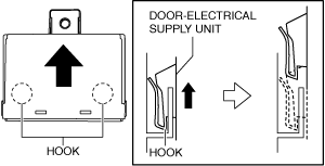
5. Lift the door-electrical supply unit in the direction of the arrow shown in the figure and remove the hooks from the service hole cover.
6. Remove the door-electrical supply unit
7. Install in the reverse order of removal.
8. If the door-electrical supply unit is replaced, perform the following procedure.
- (1) Switch the ignition ON (engine off) to complete the global central configuration (GCC) for the door-electrical supply unit (driver's or passenger's side).
-
- (2) Switch the ignition OFF.
-
- (3) Switch the ignition ON (engine off) again.
-
- (4) Clear the position memory system memory using the M-MDS. (With position memory system) (See POSITION MEMORY SYSTEM MEMORY CLEARING.)
-
- (5) Switch the ignition ON (engine off or on) and wait for 1 s or more to complete the synchronization between the door-electrical supply unit (driver's or passenger's side) and the following parts.
-
-
• Body control module (BCM)
• Electrical supply unit (ESU)
• Door-electrical supply unit (driver's or passenger's side)
- (6) Switch the ignition OFF.
-
- (7) Perform the power window system initial setting. (See POWER WINDOW SYSTEM INITIALIZATION PROCEDURE.)
-
- (8) Clear the DTC. (See CLEARING DTC.)
-