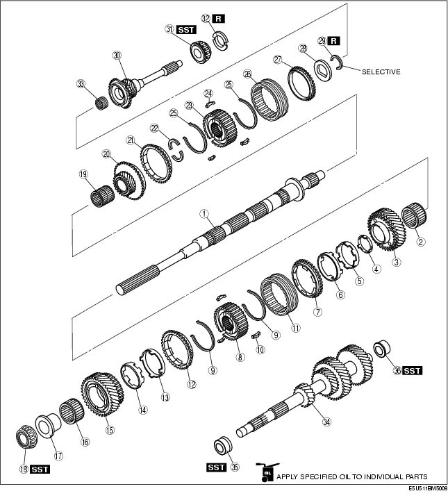
1ST/2ND GEAR COMPONENT, 5TH/6TH GEAR COMPONENT AND COUNTERSHAFT ASSEMBLY
D5E051117040M01
1. Assemble in the order indicated in the table.
|
1
|
Mainshaft
|
|
2
|
Needle bearing
|
|
3
|
2nd gear
|
|
4
|
Friction damper
|
|
5
|
Inner cone
|
|
6
|
Double cone
|
|
7
|
Synchronizer ring
|
|
8
|
1st/2nd clutch hub
|
|
9
|
Synchronizer key spring
|
|
10
|
Synchronizer key
|
|
11
|
Clutch hub sleeve
|
|
12
|
Synchronizer ring
|
|
13
|
Double cone
|
|
14
|
Inner cone
|
|
15
|
1st gear
|
|
16
|
Needle bearing
|
|
17
|
Needle bearing race
|
|
18
|
Mainshaft center bearing
|
|
19
|
Needle bearing
|
|
20
|
6th gear
|
|
21
|
Synchronizer ring
|
|
22
|
Thrust washer
|
|
23
|
Clutch hub
|
|
24
|
Synchronizer key
|
|
25
|
Synchronizer key spring
|
|
26
|
Clutch hub sleeve
|
|
27
|
Synchronizer ring
|
|
28
|
Needle bearing
|
|
29
|
Retaining ring
|
|
30
|
Maindrive gear
|
|
31
|
Maindrive gear shaft bearing
|
|
32
|
Scoop ring
|
|
33
|
Needle bearing
|
|
34
|
Countershaft
|
|
35
|
Countershaft center bearing race
|
|
36
|
Countershaft front bearing race
|
1st/2nd Clutch Hub Component Assembly Note
-
Caution
-
• Be sure to assemble the clutch hub components and synchronizer ring components while aligning the synchronizer ring grooves with the synchronizer keys.
-
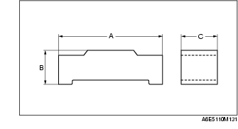
• The standard synchronizer key dimensions are as follows:

mm {in}
|
|
A
|
B
|
C
|
|
1st/2nd
|
17.0 {0.670}
|
4.7 {0.185}
|
5.0 {0.197}
|
-
• Be sure to align the synchronizer ring projections with the inner cone notches.
-
• Be sure to assemble the gears and the synchronizer ring components while aligning the double cone projections with the gear holes as shown in the figure.
-
• Align the friction damper projections with the clutch hub grooves. (2nd gear)
-
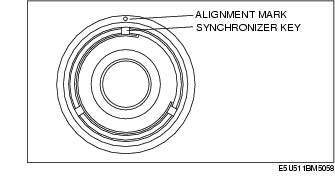
• Align the clutch hub sleeve alignment mark with the clutch hub synchronizer key installation position and assemble.

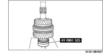
1. Using a SST and press, assemble the needle bearing, 2nd gear, synchronizer ring component (2nd), 1st/2nd clutch hub component, synchronizer ring component (1st), 1st gear, needle bearing, needle bearing race and mainshaft center bearing to the mainshaft at the same time.
-
Caution
-
• When using a press, be careful not to damage the parts.
5th/6th Clutch Hub Component Assembly Note
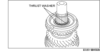
1. Place the thrust washers onto the 6th gear.
-
Note
-
• Apply petroleum jelly making sure the thrust washer does not deviate.
2. Assemble the 5th/6th clutch hub component.
-
Caution
-
• The standard synchronizer key dimensions are as follows:
mm {in}
|
|
A
|
B
|
C
|
|
5th/6th
|
17.0 {0.670}
|
4.25 {0.167}
|
5.0 {0.197}
|
-
• Align the clutch hub sleeve alignment mark with the clutch hub synchronizer key installation position and assemble.
3. Install the 5th/6th clutch hub component to the mainshaft.
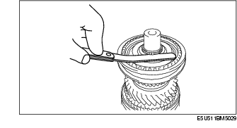
4. Install the retaining ring.
5. Measure the clearance between retaining ring and groove of the mainshaft.
-
• If not within the specification, adjust by choosing the proper retaining ring.
5th/6th clutch hub end play
-
0-0.05 mm {0-0.0019 in}
5th/6th clutch hub retaining ring
|
Thickness (mm {in})
|
|
1.50 {0.0591}
|
|
1.55 {0.0610}
|
|
1.60 {0.0630}
|
|
1.65 {0.0650}
|
|
1.70 {0.0669}
|
|
1.75 {0.0689}
|
|
1.80 {0.0709}
|
|
1.85 {0.0728}
|
|
1.90 {0.0748}
|
|
1.95 {0.0768}
|
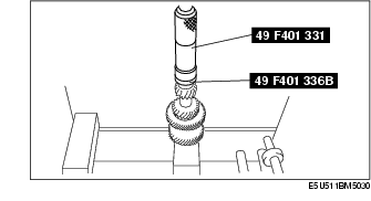
Maindrive Gear Shaft Bearing Assembly Note
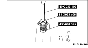
1. Assemble the maindrive gear shaft bearing using the SSTs.
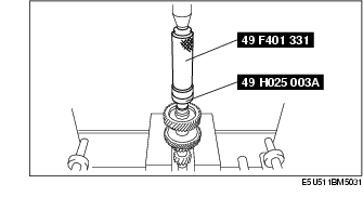
Countershaft Center Bearing Race Assembly Note
1. Assemble the countershaft center bearing race using the SSTs.
Countershaft Front Bearing Race Assembly Note
1. Assemble the countershaft front bearing race using the SSTs.