 |
amxzzw00002570
FRONT CROSSMEMBER REMOVAL/INSTALLATION
id021300801000
1. Remove the front suspension tower bar. (See FRONT SUSPENSION TOWER BAR REMOVAL/INSTALLATION.)
2. Remove the front stabilizer (See FRONT STABILIZER REMOVAL/INSTALLATION.)
3. Remove the transverse members (See TRANSVERSE MEMBER REMOVAL/INSTALLATION.)
4. Remove the steering gear and linkage, and suspend it using a cable.
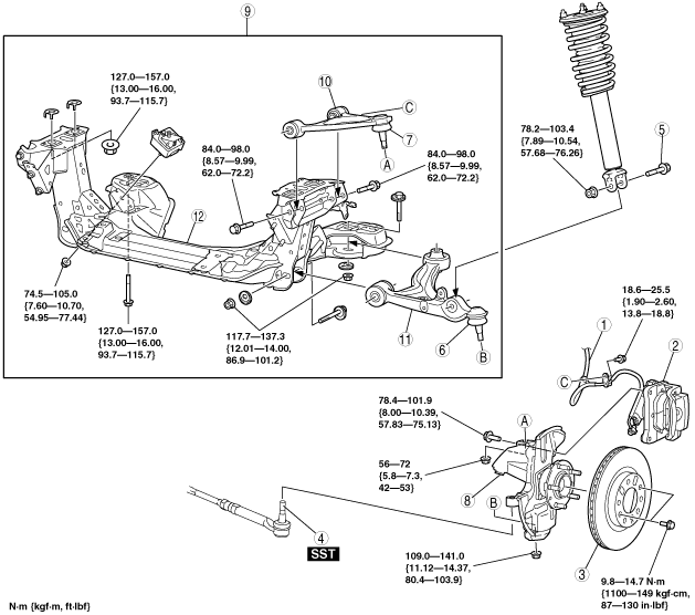
5. Remove in the order indicated in the table.
6. Install in the reverse order of removal.
7. Inspect the front wheel alignment. (See FRONT WHEEL ALIGNMENT.)
amxzzw00002570
|
|
1
|
Brake hose
|
|
2
|
Caliper and mounting support
|
|
3
|
Disc plate
|
|
4
|
Tie-rod end
|
|
5
|
Shock absorber bolt (lower)
|
|
6
|
Front lower arm bolt joint
|
|
7
|
Front upper arm ball joint
|
|
8
|
Axle and hub component
|
|
9
|
Front crossmember component
|
|
10
|
Front upper arm
|
|
11
|
Front lower arm
|
|
12
|
Front crossmember
|
Axle and Hub Component Removal Note
1. Loosen the front upper arm inner bolts.
2. Remove the axle and hub component.
Front Crossmember Component Removal Note
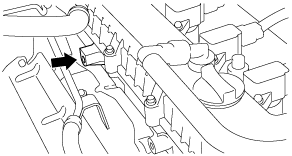
1. Secure the chain to install the SST to the position shown in the figure using the bolts (M10 x 1.5, length 30 mm {1.18 in}).
e5u213zw5019
|
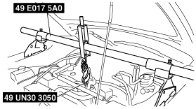
2. Suspend the engine.
e5u213zw5015
|
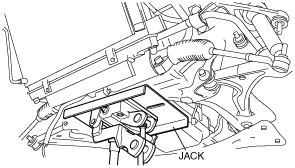
3. Support the front crossmember using a jack.
chu0213w026
|
4. Lower the front crossmember component slightly.
5. Remove the engine mounting rubber, pipes and hoses installed to the front crossmember.
6. Remove the front crossmember component.