1. Perform ABS configuration. (See ABS CONFIGURATION.)
2. Remove in the order indicated in the table.
3. Install in the reverse order of removal.
|
1
|
ABS HU/CM connector
|
|
2
|
Brake pipe
(See Brake Pipe Removal Note.)
(See Brake Pipe Installation Note.)
|
|
3
|
Nut
|
|
4
|
ABS HU/CM, brake pipe
|
|
5
|
Brake pipe (ABS HU/CM-brake pipe joint)
|
|
6
|
ABS HU/CM
|
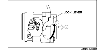
1. Pull the lock lever up in the direction of the arrow.
2. Pull the connector toward the vehicle rear and remove it.
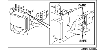
1. Place an alignment mark on the brake pipe and ABS HU/CM.
2. Apply protective tape to the connector to prevent brake fluid from entering.
3. Remove the brake pipe.
1. Align with the mark made before removing the brake pipe and temporarily install the brake pipe to the ABS HU/CM.
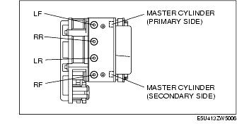
1. Align the marks made before removal and install the brake pipe to the ABS HU/CM and brake pipe joint referring to the figure.
2. Tighten the brake pipe to the specified torque using the SST (49 0259 770B).
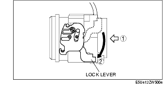
1. After connecting the connector, verify that the lock lever is completely pushed in.