Diagnostic procedure
|
STEP
|
INSPECTION
|
ACTION
|
|
|---|---|---|---|
|
1
|
VERIFY FREEZE FRAME DATA HAS BEEN RECORDED
• Has the FREEZE FRAME DATA been recorded?
|
Yes
|
Go to the next step.
|
|
No
|
Record the FREEZE FRAME DATA on the repair order, then go to the next step.
|
||
|
2
|
VERIFY RELATED REPAIR INFORMATION AVAILABILITY
• Verify related Service Bulletins and/or on-line repair information availability.
• Is any related repair information available?
|
Yes
|
Perform repair or diagnosis according to the available repair information.
• If the vehicle is not repaired, go to the next step.
|
|
No
|
Replace the TCM, then go to the next step.
|
||
|
3
|
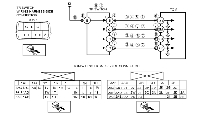
INSPECT TR SWITCH CIRCUIT
• Connect the TCM connector.
• Turn the ignition switch to the ON position. (engine off)
• Inspect the voltage between TCM terminal (wiring harness-side) and body ground.
• Are any of following terminal voltage turned on for even a moment while shifting selector lever slowly from P position to D range?
|
Yes
|
Go to Step 13.
|
|
No
|
Go to the next step.
|
||
|
4
|
INSPECT TR SWITCH CIRCUIT
• Are all terminal voltage 0 V in Step 3?
|
Yes
|
Go to Step 10.
|
|
No
|
Go to the next step.
|
||
|
5
|
INSPECT TR SWITCH CIRCUIT
• Are there two or more terminals where the voltage is abnormal in Step 3?
|
Yes
|
Adjust the TR switch, then go to Step 13.
|
|
No
|
Go to the next step.
|
||
|
6
|
INSPECT TCM CONNECTOR FOR POOR CONNECTION
• Turn the ignition switch to the LOCK position.
• Disconnect the TCM connector.
• Inspect for poor connection at TCM terminals 2O, 2K, 2M and 2N (such as damaged/pulled-out pins, corrosion).
• Is there any malfunction?
|
Yes
|
Repair or replace the connector and/or terminal, then go to Step 13.
|
|
No
|
Go to the next step.
|
||
|
7
|
INSPECT TR SWITCH SIGNAL CIRCUIT FOR SHORT TO GROUND
• Inspect for continuity between TR switch terminals (wiring harness-side) and body ground.
• Is there continuity?
|
Yes
|
Repair or replace the wiring harness for short to ground, go to Step 12.
|
|
No
|
Go to the next step.
|
||
|
8
|
INSPECT TR SWITCH CONNECTOR FOR POOR CONNECTION
• Disconnect the TR switch connector.
• Inspect for poor connection at TR switch terminals B, C, D and H (part-side) (such as damaged/pulled-out pins, corrosion)
• Are TR switch terminals normal?
|
Yes
|
Go to the next step.
|
|
No
|
Repair terminals or replace the TR switch, then go to Step 13.
|
||
|
9
|
INSPECT TR SWITCH
• Inspect the TR switch.
• Is the TR switch normal?
|
Yes
|
Repair or replace the wiring harness for open circuit, then go to Step 13.
|
|
No
|
Replace the TR switch, then go to Step 13.
|
||
|
10
|
INSPECT TR SWITCH POWER CIRCUIT FOR OPEN CIRCUIT
• Turn the ignition switch to the LOCK position.
• Disconnect the TR switch connector.
• Turn the ignition switch to the ON position (engine off).
• Inspect the voltage at TR switch (wiring harness-side) terminal E.
• Is there B+ at TR switch (wiring harness-side) terminal E?
|
Yes
|
Go to the next step.
|
|
No
|
Inspect the METER 15A fuse.
• If normal, repair or replace the wiring harness, then go to Step 13.
|
||
|
11
|
INSPECT TR SWITCH CONNECTOR FOR POOR CONNECTION
• Disconnect the TR switch connector.
• Inspect for poor connection at TR switch terminal E (part-side) (such as damaged/pulled-out pins, corrosion)
• Are TR switch terminals normal?
|
Yes
|
Go to the next step.
|
|
No
|
Repair terminals or replace the TR switch, then go to Step 13.
|
||
|
12
|
INSPECT TR SWITCH
• Inspect the TR switch.
• Is the TR switch normal?
|
Yes
|
Go to the next step.
|
|
No
|
Replace the TR switch, then go to the next step.
|
||
|
13
|
VERIFY TROUBLESHOOTING OF DTC P0707 COMPLETED
• Make sure to reconnect all the disconnected connectors.
• Clear the DTC from the memory using the M-MDS.
• Drive the vehicle in each range (P-D).
• Is same DTC present?
|
Yes
|
Replace the TCM, then go to the next step.
|
|
No
|
Go to the next step.
|
||
|
14
|
VERIFY AFTER REPAIR PROCEDURE
• Perform the "After Repair Procedure".
• Are any DTCs present?
|
Yes
|
Go to the applicable DTC inspection.
(See DTC TABLE [SJ6A-EL].)
|
|
No
|
Troubleshooting completed.
|
||