DTC B104D, B2226, B2227, B2856
id080200004500
DTC |
B104D |
Crash zone sensor assembly incorrect |
---|---|---|
B2226 |
Crash zone sensor system internal circuit disabled |
|
B2227 |
Crash zone sensor system communication error |
|
B2856 |
Crash zone sensor system communication data error |
|
DETECTION CONDITION
|
• The SAS control module detects an error of impact magnitude set in the sensor, which occurs due to installation mismatch of the crash zone sensor or side air bag sensors.
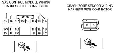
• Malfunction in wiring harness between crash zone sensor and SAS control module
• Malfunction in crash zone sensor circuit
|
|
POSSIBLE CAUSE
|
• Crash zone sensor mis-installed with wrong sensor
• Crash zone sensor connector malfunction
• Open or short circuit in the wiring harness between the crash zone sensor and SAS control module
• Crash zone sensor malfunction
• SAS control module malfunction
|
|
![]() |
Diagnostic procedure
STEP |
INSPECTION |
ACTION |
|
---|---|---|---|
1
|
INSPECT CRASH ZONE SENSOR CONNECTOR
• Turn the ignition switch to the LOCK position.
• Remove the battery cover.
• Disconnect the negative battery cable and wait for 1 min or more. (See BATTERY REMOVAL/INSTALLATION [L8, LF].)
• Remove the front bumper. (See FRONT BUMPER REMOVAL/INSTALLATION.)
• Disconnect the crash zone sensor connector. (See CRASH ZONE SENSOR REMOVAL/INSTALLATION.)
• Inspect the crash zone sensor connector. (Corrosion, damage, and disconnected pins)
• Is there any malfunction of the crash zone sensor connector?
|
Yes
|
Replace the crash zone sensor wiring harness.
|
No
|
Go to the next step.
|
||
2
|
INSPECT WIRING HARNESS BETWEEN SAS CONTROL MODULE AND CRASH ZONE SENSOR
• Remove the column cover.
• Disconnect the clock spring connector.
• Remove the glove compartment.
• Disconnect the passenger-side air bag module connector.
• Disconnect the driver and passenger-side seat connectors.
(See SEAT REMOVAL/INSTALLATION.)
• Remove the back trim.
• Remove the driver and passenger-side pre-tensioner seat belt connectors.
• Remove the console panel.
• Disconnect the SAS control module connectors.
• Inspect the wiring harnesses between SAS control module connector terminal 1E and crash zone sensor connector terminal A, SAS control module connector terminal 1B and crash zone sensor connector terminal B for the following:
• Is the wiring harness normal?
|
Yes
|
Go to the next step.
|
No
|
Replace the wiring harness between the SAS control module and the crash zone sensor.
|
||
3
|
INSPECT THE WIRING HARNESS BETWEEN THE SAS CONTROL MODULE AND CRASH ZONE SENSOR FOR A SHORT CIRCUIT TO THE POWER SUPPLY
• Connect the negative battery cable.
• Turn the ignition switch to the ON position with SAS control module and crash zone sensor connector disconnected.
• Measure the voltage of SAS control module connector terminals 1B and 1E.
• Is the voltage measured?
|
Yes
|
Replace the wiring harness between the SAS control module and the crash zone sensor.
|
No
|
Replace the crash zone sensor, then go to the next step.
|
||
4
|
PERFORM SAS CONTROL MODULE DTC INSPECTION
• Turn the ignition switch to the LOCK position.
• Disconnect the negative battery cable and wait for 1min or more.
• Connect the crash zone sensor connector.
• Connect the SAS control module connectors.
• Connect the negative battery cable.
• Turn the ignition switch to the ON position.
• Clear the DTC for the SAS control module using the M-MDS.
(See CLEARING DTC.)
• Perform the DTC inspection for the SAS control module using the M-MDS.
(See DTC DISPLAY.)
• Are the same DTCs present?
|
Yes
|
Replace the SAS control module.
|
No
|
DTC troubleshooting completed.
|