DTC B1871


id080200810100

DTC B1871
Passenger air bag deactivation (PAD) switch system circuit disabled
DETECTION CONDITION
Warning
•  Detection conditions are for understanding DTC outline before performing inspection. Performing inspection with only detection conditions may cause injury due to operating error or damage the system. When performing inspection, always follow inspection procedure.
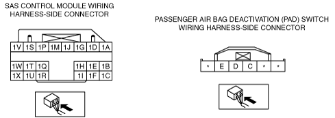
•  Malfunction in wiring harness between PAD switch and SAS control module
•  Malfunction in PAD switch circuit
POSSIBLE CAUSE
•  PAD switch connector malfunction
•  PAD switch assembly incorrect
•  Open or short circuit in wiring harness between PAD switch and SAS control module
•  Open circuit in wiring harness between PAD switch and body ground
•  SAS control module malfunction

Diagnostic procedure

STEP

INSPECTION

ACTION

1
INSPECT PAD SWITCH CONNECTOR
Warning
•  Handling the component parts improperly can accidentally operate (deploy) the air bag module, which may seriously injure you. Read the service warnings/cautions and the workshop manual before handling the air bag system components.
•  Turn the ignition switch to the LOCK position.
•  Remove the battery cover.
•  Disconnect the negative battery cable and wait for 1 min or more. (See BATTERY REMOVAL/INSTALLATION [L8, LF].)
•  Disconnect the PAD switch connector.
•  Inspect the PAD switch connector. (Corrosion, damage, and disconnected pins)
•  Is there any malfunction of the PAD switch connector?
Yes
Replace the PAD switch wiring harness.
No
Go to the next step.
2
INSPECT PAD SWITCH
•  Inspect the PAD switch.
•  Is the PAD switch normal?
Yes
Go to the next step.
No
Replace the PAD switch.
3
INSPECT WIRING HARNESS BETWEEN PAD SWITCH AND SAS CONTROL MODULE
•  Remove the column cover.
•  Disconnect the clock spring connector.
•  Remove the glove compartment.
•  Disconnect the passenger-side air bag module connector. (See PASSENGER-SIDE AIR BAG MODULE REMOVAL/INSTALLATION.)
•  Disconnect the driver and passenger-side seat connectors.
•  Remove the back trim.
•  Remove the driver and passenger-side pre-tensioner seat belt connectors.
•  Remove the console panel.
•  Disconnect the SAS control module connectors.
•  Inspect the wiring harness between SAS control module connector terminal 1Q and PAD switch connector terminal D, SAS control module connector terminal 1H and PAD switch connector terminal C for the following:
―  Short circuit between terminals
―  Short to body ground
―  Open circuit
Note
•  Inspect for continuity while shaking the wiring harness between the SAS control module and PAD switch.
•  Is the wiring harness normal?
Yes
Go to the next step.
No
Replace the wiring harness between the SAS control module and the PAD switch.
4
INSPECT WIRING HARNESS BETWEEN PAD SWITCH AND BODY GROUND
•  Inspect the wiring harness between PAD switch connector terminal E and body ground for the following:
―  Open circuit
Note
•  Inspect for continuity while shaking the wiring harness between the SAS control module and PAD switch.
•  Is the wiring harness normal?
Yes
Go to the next step.
No
Replace the wiring harness between the PAD switch and body ground.
5
PERFORM SAS CONTROL MODULE DTC INSPECTION
•  Turn the ignition switch to the LOCK position.
•  Disconnect the negative battery cable and wait for 1min or more.
•  Reconnect all disconnected connectors.
•  Connect the negative battery cable.
•  Turn the ignition switch to the ON position.
•  Clear the DTC for the SAS control module using the M-MDS.
•  Perform the DTC inspection for the SAS control module using the M-MDS.
•  Are the same DTCs present?
Yes
Replace the SAS control module.
No
DTC troubleshooting completed.