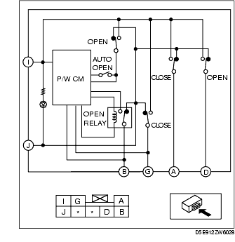
1. Measure the voltage at each terminal (other than terminal J).
2. Remove the battery cover.
3. Disconnect the negative battery cable.(See BATTERY REMOVAL/INSTALLATION [L8, LF].)
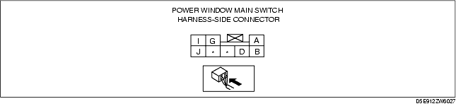
4. Inspect the power window main switch connector for continuity at terminal J.
5. If the system does not work properly even though the inspection items or related wiring harnesses do not have any malfunction, replace the power window main switch.
|
Terminal
|
Signal name
|
Connected to
|
Measured condition
|
Voltage (V)/Continuity
|
Inspection item (s)
|
|---|---|---|---|---|---|
|
B
|
Open output
|
Power window motor
|
While door glass is opening
|
B+
|
• Power window motor (See POWER WINDOW MOTOR INSPECTION.)
• Related wiring harnesses
|
|
While door glass is closing
|
1.0 or less
|
||||
|
G
|
Close output
|
Power window motor
|
While door glass is opening
|
1.0 or less
|
• Power window motor (See POWER WINDOW MOTOR INSPECTION.)
• Related wiring harnesses
|
|
While door glass is closing
|
B+
|
||||
|
I
|
Power supply
|
P/WIND 20A fuse
|
Ignition switch at ON
|
B+
|
• P/WIND 20A fuse
• Related wiring harnesses
|
|
J
|
GND
|
Body ground
|
Under any condition : Inspect for continuity to ground
|
Continuity detected
|
• GND
|
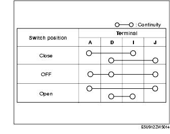
1. Verify that the continuity between the power window main switch terminals is as indicated in the table.
2. Apply battery positive voltage to terminal I, and connect the ground to terminal J, and then verify that the light emitting diode illuminates.
1. Measure the voltage at each terminal (other than terminal A).
2. Remove the battery cover.
3. Disconnect the negative battery cable.(See BATTERY REMOVAL/INSTALLATION [L8, LF].)
4. Inspect the power window main switch connector for continuity at terminal A.
5. If the system does not work properly even though the inspection items or related wiring harnesses do not have any malfunction, replace the power window main switch.

|
Terminal
|
Signal name
|
Connected to
|
Measured condition
|
Voltage (V)/Continuity
|
Inspection item (s)
|
|---|---|---|---|---|---|
|
A
|
GND
|
Body ground
|
Under any condition : Inspect for continuity to ground
|
Continuity detected
|
• GND
|
|
B
|
Open output
|
Power window motor
|
While door glass is opening
|
B+
|
• Power window motor (See POWER WINDOW MOTOR INSPECTION.)
• Related wiring harnesses
|
|
While door glass is closing
|
1.0 or less
|
||||
|
G
|
Close output
|
Power window motor
|
While door glass is opening
|
1.0 or less
|
• Power window motor (See POWER WINDOW MOTOR INSPECTION.)
• Related wiring harnesses
|
|
While door glass is closing
|
B+
|
||||
|
I
|
Power supply
|
P/WIND 20A fuse
|
Ignition switch at ON
|
B+
|
• P/WIND 20A fuse
• Related wiring harnesses
|
1. Verify that the continuity between the power window main switch terminals is as indicated in the table.
2. Apply battery positive voltage to terminal I, and connect the ground to terminal A, and then verify that the light emitting diode illuminates.
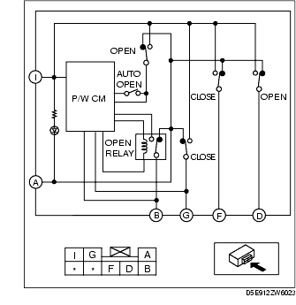
1. Measure the voltage at each terminal (other than terminal G).
2. Remove the battery cover.
3. Disconnect the negative battery cable.(See BATTERY REMOVAL/INSTALLATION [L8, LF].)
4. Inspect the power window main switch connector for continuity at terminal G.
5. If the system does not work properly even though the inspection items or related wiring harnesses do not have any malfunction, replace the power window main switch.

|
Terminal
|
Signal name
|
Connected to
|
Measured condition
|
Voltage (V)/Continuity
|
Inspection item (s)
|
|---|---|---|---|---|---|
|
G
|
GND
|
Body ground
|
Under any condition : Inspect for continuity to ground
|
Continuity detected
|
• GND
|
|
J
|
Open output
|
Power window motor (LH)
|
While door glass is opening
|
B+
|
• Power window motor (See POWER WINDOW MOTOR INSPECTION.)
• Related wiring harnesses
|
|
While door glass is closing
|
1.0 or less
|
||||
|
I
|
Close output
|
Power window motor (LH)
|
While door glass is opening
|
1.0 or less
|
• Power window motor (See POWER WINDOW MOTOR INSPECTION.)
• Related wiring harnesses
|
|
While door glass is closing
|
B+
|
||||
|
F
|
Open output
|
Power window motor (RH)
|
While door glass is opening
|
B+
|
• Power window motor (See POWER WINDOW MOTOR INSPECTION.)
• Related wiring harnesses
|
|
While door glass is closing
|
1.0 or less
|
||||
|
D
|
Close output
|
Power window motor (RH)
|
While door glass is opening
|
1.0 or less
|
• Power window motor (See POWER WINDOW MOTOR INSPECTION.)
• Related wiring harnesses
|
|
While door glass is closing
|
B+
|
||||
|
B
|
Power supply
|
P/WIND 20A fuse
|
Ignition switch at ON
|
B+
|
• P/WIND 20A fuse
• Related wiring harnesses
|