Inspection procedure
|
STEP
|
INSPECTION
|
ACTION
|
|
|---|---|---|---|
|
1
|
INSPECT POWER SUPPLY CIRCUIT OF DISCHARGE HEADLIGHT CONTROL MODULE
• Disconnect the discharge headlight control module connector.
• Turn the headlight switch to the HEADLIGHT (LO) position.
• Measure the voltage at discharge headlight control module terminal C (wiring harness-side).
• Is the voltage approx. 12 V?
|
Yes
|
Go to Step 6.
|
|
No
|
Go to the next step.
|
||
|
2
|
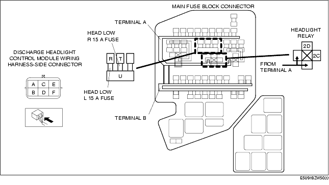
INSPECT FUSE
• Turn the headlight switch to the OFF position.
• Remove the HEAD LOW R 15 A fuse (RH) or HEAD LOW L 15 A fuse (LH).
• Inspect the fuses.
• Are the fuses normal?
|
Yes
|
Go to the next step.
|
|
No
|
Replace the fuse.
|
||
|
3
|
INSPECT HEADLIGHT RELAY
• Remove the headlight relay. (See RELAY LOCATION.)
• Inspect the headlight relay. (See RELAY INSPECTION.)
• Is the headlight relay normal?
|
Yes
|
Go to the next step.
|
|
No
|
Replace the headlight relay. (See RELAY LOCATION.)
|
||
|
4
|
INSPECT LIGHT SWITCH
• Inspect the light switch. (See LIGHT SWITCH INSPECTION.)
• Is the light switch normal?
|
Yes
|
Go to the next step.
|
|
No
|
Replace the light switch. (See LIGHT SWITCH REMOVAL/INSTALLATION.)
|
||
|
5
|
INSPECT WIRING HARNESS BETWEEN BATTERY AND DISCHARGE HEADLIGHT CONTROL MODULE
• Remove the battery cover.
• Disconnect the negative battery cable. (See BATTERY REMOVAL/INSTALLATION [L8, LF].)
• Inspect for continuity between the following terminals:
• Are the wiring harnesses normal?
|
Yes
|
Go to the next step.
|
|
No
|
Replace the related wiring harness.
|
||
|
6
|
INSPECT WIRING HARNESS BETWEEN DISCHARGE HEADLIGHT CONTROL MODULE AND GROUND
• Inspect wiring harness between discharge headlight control module terminal F and ground for following:
• Inspect the headlight relay. (See RELAY INSPECTION.)
• Is the wiring harness normal?
|
Yes
|
Go to the next step.
|
|
No
|
Replace the related wiring harness.
|
||
|
7
|
VERIFY WHETHER MALFUNCTION IS IN DISCHARGE HEADLIGHT BULB OR DISCHARGE HEADLIGHT CONTROL UNIT
• Install any other discharge headlight low bulb (previously verified as illumination normally). (See HEADLIGHT BULB REMOVAL/INSTALLATION.)
• Connect the discharge headlight control module connector.
• Turn the headlight switch to the HEADLIGHT (LO) position.
• Does the headlight (low-beam) illuminate?
|
Yes
|
System inspection completed.
|
|
No
|
Replace the front combination light. (See FRONT COMBINATION LIGHT REMOVAL/INSTALLATION.)
|
||