 |
amxzzw00000604
ON-BOARD DIAGNOSTIC TEST [L8, LF]
id0102b1801000
DTC Reading Procedure
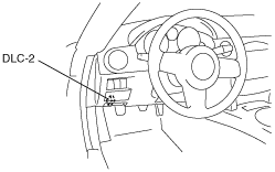
1. Connect the M-MDS to the DLC-2.
amxzzw00000604
|
2. After the vehicle is identified, select the following items from the initial screen of the M-MDS.
3. Then, select the “Retrieve CMDTCs” and perform procedures according to directions on the M-MDS screen.
4. Verify the DTC according to the directions on the M-MDS screen.
5. After completion of repairs, clear all DTCs stored in the PCM, while referring to “AFTER REPAIR PROCEDURE”. (See AFTER REPAIR PROCEDURE [L8, LF].)
Pending Trouble Code Access Procedure
1. Connect the M-MDS to the DLC-2.
amxzzw00000604
|
2. After the vehicle is identified, select the following items from the initial screen of the M-MDS.
3. Then, select the “Retrieve CMDTCs” and perform procedures according to directions on the M-MDS screen.
4. Retrieve the pending trouble codes according to the directions on the M-MDS screen.
Freeze Frame PID Data Access Procedure
1. Connect the M-MDS to the DLC-2.
amxzzw00000604
|
2. After the vehicle is identified, select the following items from the initial screen of the M-MDS.
3. Then, select the “Retrieve CMDTCs” and perform procedures according to directions on the M-MDS screen.
4. Retrieve the freeze frame PID data according to the directions on the M-MDS screen.
Freeze frame data table (mode2, mode12) table
|
Freeze frame data item |
Unit |
Description |
Corresponding PID data monitor item |
|||||
|---|---|---|---|---|---|---|---|---|
|
FUELSYS1
|
Open Loop/Closed Loop/OL-Drive/OL-Fault/CL-Fault
|
Fuel system status
|
FUELSYS
|
|||||
|
LOAD
|
%
|
Calculated engine load
|
—
|
|||||
|
ECT
|
°C
|
°F
|
Engine coolant temperature
|
ECT
|
||||
|
SFT1
|
%
|
Short term fuel trim
|
SHRTFT1
|
|||||
|
LFT1
|
%
|
Long term fuel trim
|
LONGFT1
|
|||||
|
MAP
|
kPa
|
Bar
|
psi
|
Manifold absolute pressure
|
MAP
|
|||
|
RPM
|
RPM
|
Engine speed
|
RPM
|
|||||
|
VS
|
KPH
|
MPH
|
Vehicle speed
|
VSS
|
||||
|
SPARKADV
|
°
|
Ignition timing
|
SPARKADV
|
|||||
|
IAT
|
°C
|
°F
|
Intake air temperature
|
IAT
|
||||
|
MAF
|
g/sec
|
Mass airflow
|
MAF
|
|||||
|
TP
|
%
|
Throttle valve position No.1
|
TP1
|
|||||
|
RUNTM
|
hh:mm:ss
|
Time from engine start
|
—
|
|||||
|
EGRPCT
|
%
|
Target EGR valve position
|
SEGRP_DSD
|
|||||
|
EVAPPCT
|
%
|
Purge solenoid valve controlled value
|
EVAPCP
|
|||||
|
WARMUPS
|
—
|
Number of warm-up cycle after DTC cleared
|
—
|
|||||
|
CLRDIST
|
Miles
|
Mileage after DTC cleared
|
—
|
|||||
|
BARO
|
kPa
|
Bar
|
psi
|
Barometric pressure
|
BARO
|
|||
|
CATTEMP11
|
°C
|
°F
|
Estimated catalytic converter temperature
|
CATT11_DSD
|
||||
|
VPWR
|
V
|
Module supply voltage
|
VPWR
|
|||||
|
ALV
|
%
|
Engine load
|
LOAD
|
|||||
|
TP_REL
|
%
|
Relative throttle position
|
TP REL
|
|||||
|
TP_B
|
%
|
Throttle valve position No.2
|
TP2
|
|||||
|
APP_D
|
%
|
Accelerator pedal position No.1
|
APP1
|
|||||
|
APP_E
|
%
|
Accelerator pedal position No.2
|
APP2
|
|||||
|
TAC_PCT
|
%
|
Target throttle valve position
|
ETC_DSD
|
|||||
On-Board System Readiness Tests Access Procedure
1. Connect the M-MDS to the DLC-2.
amxzzw00000604
|
2. After the vehicle is identified, select the following items from the initial screen of the M-MDS.
3. Then, select the “***SUP” and “***EVAL” PIDs in the PID selection screen.
4. Monitor those PIDs and check it system monitor is completed.
PID/DATA Monitor and Record Procedure
1. Connect the M-MDS to the DLC-2.
amxzzw00000604
|
2. After the vehicle is identified, select the following items from the initial screen of the M-MDS.
3. Select the PID from the PID table.
4. Verify the PID data according to the directions on the screen.
Diagnostic Monitoring Test Results Access Procedure
1. Connect the M-MDS to the DLC-2.
amxzzw00000604
|
2. After the vehicle is identified, select the following items from the initial screen of the M-MDS.
3. Verify the diagnostic monitoring test result according to the directions on the screen.
Simulation Function Procedure
1. Connect the M-MDS to the DLC-2.
amxzzw00000604
|
2. After the vehicle is identified, select the following items from the initial screen of the M-MDS.
3. Select the simulation items from the PID table.
4. Perform the simulation function, inspect the operations for each parts.