amxzzw00000834
|
VARIABLE TUMBLE SHUTTER VALVE ACTUATOR REMOVAL/INSTALLATION [L8, LF]
id0113a3804900
1. Remove the battery cover. (See BATTERY REMOVAL/INSTALLATION [L8, LF].)
2. Disconnect the negative battery cable. (See BATTERY REMOVAL/INSTALLATION [L8, LF].)
3. Remove the throttle body. (See INTAKE-AIR SYSTEM REMOVAL/INSTALLATION [L8, LF].)
4. Disconnect the quick release connector (Type A). (See QUICK RELEASE CONNECTOR (EMISSION SYSTEM) REMOVAL/INSTALLATION [L8, LF].)
5. Remove the plug hole plate. (See PLUG HOLE PLATE REMOVAL/INSTALLATION [L8, LF].)
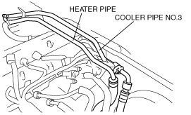
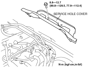
6. Remove the following parts:
amxzzw00000834
|
amxzzw00000835
|
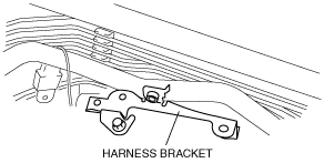
7. Remove the harness bracket.
amxzzw00000809
|
8. Remove the under cover. (See TRANSVERSE MEMBER REMOVAL/INSTALLATION.)
9. Follow “BEFORE SERVICE PRECAUTION” before performing any work operations to prevent fuel from spilling from the fuel system. (See BEFORE SERVICE PRECAUTION [L8, LF].)
10. Disconnect the quick release connector from the fuel distributor. (See QUICK RELEASE CONNECTOR (FUEL SYSTEM) REMOVAL/INSTALLATION [L8, LF].)
11. Remove the fuel distributor. (See FUEL INJECTOR REMOVAL/INSTALLATION [L8, LF].)
12. Move the clutch release cylinder slightly out of the way. (MT) (See CLUTCH RELEASE CYLINDER REMOVAL/INSTALLATION.)
13. Remove the dynamic chamber. (See INTAKE-AIR SYSTEM REMOVAL/INSTALLATION [L8, LF].)
14. Remove the intake manifold. (See INTAKE-AIR SYSTEM REMOVAL/INSTALLATION [L8, LF].)
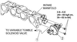
15. Remove in the order indicated in the table.
amxzzw00000810
|
|
1
|
Vacuum hose
|
|
2
|
Variable tumble shutter valve actuator
|
16. Install in the reverse order of removal.
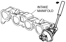
Variable Tumble Shutter Valve Actuator Removal Note
1. Disengage the variable tumble shutter valve actuator rod from the intake manifold using a suitable screwdriver or equivalent tool as shown in the figure.
amxzzw00000811
|
Variable Tumble Shutter Valve Actuator Installation Note
1. Press the variable tumble shutter valve actuator into the variable tumble shutter valve actuator rod and the intake manifold on the opposite side until a click is heard, and install it.