 |
amxzzw00002038
INTAKE-AIR SYSTEM REMOVAL/INSTALLATION [L8, LF]
id0113a3801900
1. Remove the battery cover. (See BATTERY REMOVAL/INSTALLATION [L8, LF].)
2. Disconnect the negative battery cable. (See BATTERY REMOVAL/INSTALLATION [L8, LF].)
3. Remove in the order indicated in the table.
4. Install in the reverse order of removal.
5. Add the engine coolant to the cooling system filler neck and the coolant reserve tank to replace that during servicing.
6. Inspect the engine coolant level. (See ENGINE COOLANT LEVEL INSPECTION [L8, LF].)
7. Inspect for engine coolant leakage. (See ENGINE COOLANT LEAKAGE INSPECTION [L8, LF].)
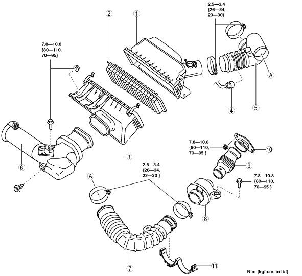
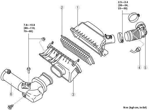
Step 1 (Except 6MT)
amxzzw00002038
|
|
1
|
Air cleaner cover
|
|
2
|
Air cleaner element
|
|
3
|
Air cleaner case
|
|
4
|
Quick release connector
|
|
5
|
Air hose
|
|
6
|
Fresh-air duct
(See Fresh-air Duct Removal Note.)
|
Step 1 (6MT)
amxzzw00002627
|
|
1
|
Air cleaner cover
|
|
2
|
Air cleaner element
|
|
3
|
Air cleaner case
|
|
4
|
Quick release connector
|
|
5
|
Air hose
|
|
6
|
Fresh-air duct
(See Fresh-air Duct Removal Note.)
|
|
7
|
Air intake hose
|
|
8
|
Resonance chamber No. 2
|
|
9
|
Resonance duct No. 1
|
|
10
|
Resonance duct No. 2
|
|
11
|
Hose clamp
|
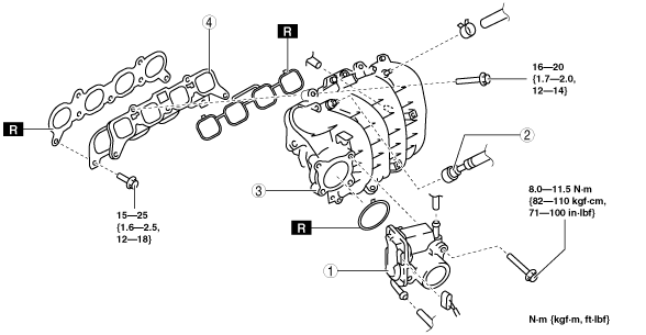
Step 2
amxzzw00002628
|
|
1
|
Throttle body
(See Throttle Body Removal Note.)
|
|
2
|
Quick release connector
|
|
3
|
Dynamic chamber
(See Dynamic Chamber Removal Note.)
|
|
4
|
Intake manifold
(See Intake Manifold Removal Note.)
|
Air Cleaner Cover Removal Note
1. Remove the MAF/IAT sensor. (See MASS AIR FLOW (MAF)/INTAKE AIR TEMPERATURE (IAT) SENSOR REMOVAL/INSTALLATION [L8, LF].)
2. Remove the air cleaner cover.
Fresh-air Duct Removal Note
1. Remove the front bumper. (See FRONT BUMPER REMOVAL/INSTALLATION.)
2. Remove the fresh-air duct.
Throttle Body Removal Note
1. Wrap a clean cloth around the cooling system cap and release the pressure by loosening the cap slowly.
2. Remove the water hose from the throttle body and plug the water hose quickly.
3. Remove the throttle body.
Dynamic Chamber Removal Note
1. Remove the plug hole plate. (See PLUG HOLE PLATE REMOVAL/INSTALLATION [L8, LF])
2. Follow “BEFORE SERVICE PRECAUTION” before performing any work operations to prevent fuel from spilling from the fuel system. (See BEFORE SERVICE PRECAUTION [L8, LF].)
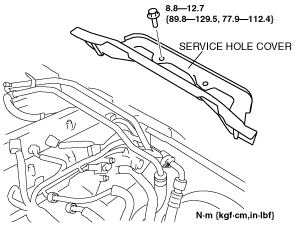
3. Remove the following parts:
amxzzw00002629
|
amxzzw00002630
|
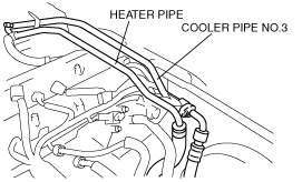
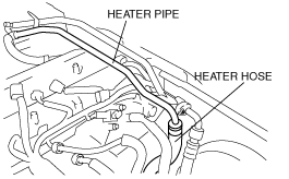
4. Disconnect the heater hose and move the heater pipe slightly out of the way. (L.H.D.)
amxzzw00002631
|
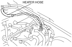
5. Disconnect the heater hose and move the heater hose slightly out of the way. (L.H.D.)
amxzzw00002171
|
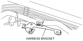
6. Remove the harness bracket.
amxzzw00002632
|
7. Remove the under cover. (See TRANSVERSE MEMBER REMOVAL/INSTALLATION.)
8. Disconnect the variable intake air solenoid valve connector, variable tumble solenoid valve connector, EGR valve connector, CMP sensor connector and PSP switch connector.
9. Disconnect the ignition coil connector and fuel injector connector and move the harness slightly out of the way.
10. Disconnect the quick release connector from the fuel distributor. (See QUICK RELEASE CONNECTOR (FUEL SYSTEM) REMOVAL/INSTALLATION [L8, LF].)
11. Remove the fuel distributor. (See FUEL INJECTOR REMOVAL/INSTALLATION [L8, LF].)
12. Disconnect the water hose from the EGR valve.
13. Disconnect two water hoses from the thermostat.
14. Remove the heater hose and heater pipe from the dynamic chamber.
15. Remove the variable intake air solenoid valve. (See VARIABLE INTAKE AIR SOLENOID VALVE REMOVAL/INSTALLATION [L8, LF].)
16. Remove the variable tumble solenoid valve. (See VARIABLE TUMBLE SOLENOID VALVE REMOVAL/INSTALLATION [L8, LF].)
17. Remove the dynamic chamber installation bolts.
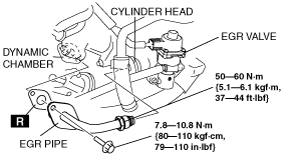
18. Remove the EGR pipe.
amxzzw00002633
|
19. Disconnect the connector from the A/C compressor.
20. Disconnect the KS connector.
21. Move the vacuum hose between the purge solenoid valve and the charcoal canister slightly out of the way.
22. Move the clutch release cylinder slightly out of the way. (MT) (See CLUTCH RELEASE CYLINDER REMOVAL/INSTALLATION.)
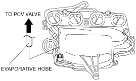
23. Disconnect the evaporative hose with the dynamic chamber raised.
amxzzw00002154
|
24. Remove the dynamic chamber.
25. Remove the variable intake air shutter valve actuator. (See VARIABLE INTAKE AIR SHUTTER VALVE ACTUATOR REMOVAL/INSTALLATION [L8, LF].)
26. Remove the MAP sensor. (See MANIFOLD ABSOLUTE PRESSURE (MAP) SENSOR REMOVAL/INSTALLATION [L8, LF].)
Intake Manifold Removal Note
1. Remove the intake manifold.
2. Remove the variable tumble shutter valve actuator. (See VARIABLE TUMBLE SHUTTER VALVE ACTUATOR REMOVAL/INSTALLATION [L8, LF].)
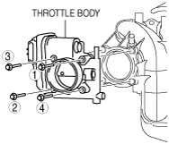
Throttle Body Installation Note
1. Tighten the bolts in the order as shown in the figure.
amxzzw00002634
|
2. Remove the plug from the water hose and install the water hose to the throttle body quickly.