 |
amxzzw00005850
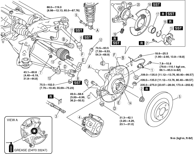
WHEEL HUB, REAR KNUCKLE REMOVAL/INSTALLATION
id031200803000
1. When working on the left side of the vehicle, disconnect the rear auto leveling sensor link. (Vehicle with discharge headlight system) (See REAR AUTO LEVELING SENSOR REMOVAL/INSTALLATION.)
2. Remove in the order indicated in the table.
3. Install in the reverse order of removal.
4. After installation, inspect rear wheel alignment. (See REAR WHEEL ALIGNMENT.)
amxzzw00005850
|
|
1
|
ABS wheel-speed sensor
|
|
2
|
Locknut
(See Locknut Removal Note.)
(See Locknut Installation Note.)
|
|
3
|
Parking brake cable
|
|
4
|
Brake calliper component
|
|
5
|
Disc plate
|
|
6
|
Rear lateral link (upper) ball joint
|
|
7
|
Stabilizer control link nut (lower)
|
|
8
|
Rear lateral link (lower) ball joint
|
|
9
|
Shock absorber bolt (lower)
|
|
10
|
Toe control link ball joint
|
|
11
|
Rear trailing link (upper) ball joint
|
|
12
|
Rear trailing link (lower) outside bolt
|
|
13
|
Rear drive shaft
|
|
14
|
Rear knuckle component
|
|
15
|
Wheel hub component
|
|
16
|
Retaining ring
|
|
17
|
Wheel bearing
(See Wheel Bearing Removal Note.)
|
|
18
|
Dust cover
(See Dust Cover Removal Note.)
(See Dust Cover Installation Note.)
|
|
19
|
Bushing
(See Bushing Removal Note.)
(See Bushing Installation Note.)
|
|
20
|
Rear knuckle
|
|
21
|
Wheel hub bolt
(See Wheel Hub Bolt Removal Note.)
|
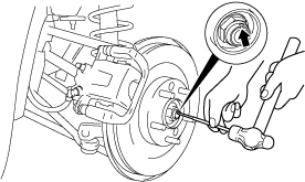
Locknut Removal Note
1. Lock the disc plate by applying the brakes.
2. Knock the crimped portion of the locknut outward using a chisel and a hammer.
amxzzw00001241
|
3. Remove the locknut.
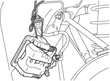
Brake Caliper Component Removal Note
1. Suspend the brake calliper component using a cable or equivalent.
amxzzw00001242
|
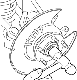
Rear Drive shaft Removal Note
1. Temporarily install a spare nut onto the end of the rear drive shaft.
2. Tap the nut with a copper hammer to loosen the drive shaft from the wheel hub.
amxzzw00001243
|
3. Separate the rear drive shaft from the wheel hub.
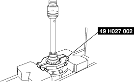
Wheel Hub Component Removal Note
1. Wind the SST and backing plate contact area with packing tape two times.
2. Remove the wheel hub component using the SSTs.
amxzzw00001244
|
3. If the bearing inner race remains on the wheel hub component, use a chisel to secure a sufficient space for installing the SST between wheel hub component and bearing inner race.
amxzzw00001245
|
4. Remove the bearing inner race using the SST.
amxzzw00001246
|
5. After removing the bearing, repair any backing plate deformation.
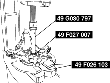
Wheel Bearing Removal Note
1. Wind the SST and backing plate contact area with packing tape two times.
2. Remove the wheel bearing from the rear knuckle using the SSTs.
amxzzw00001247
|
3. After removing the bearing, repair any backing plate deformation.
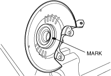
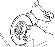
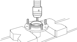
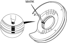
Dust Cover Removal Note
1. Place an alignment mark on the dust cover and rear knuckle for proper installation.
amxzzw00002423
|
2. Remove the dust cover using a chisel.
amxzzw00001248
|
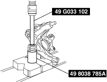
Bushing Removal Note
1. Remove the bushing from the rear knuckle using the SSTs.
amxzzw00001249
|
Wheel Hub Bolt Removal Note
1. Remove the wheel hub bolts from the wheel hub using a press.
amxzzw00001250
|
Wheel Hub Bolt Installation Note
1. Press in new wheel hub bolts into the wheel hub using a press.
amxzzw00001251
|
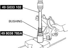
Bushing Installation Note
1. Press the new bushing into the rear knuckle using the SSTs.
amxzzw00002424
|
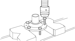
Dust Cover Installation Note
1. Align the new and old dust covers and place alignment marks on the new dust cover.
amxzzw00002425
|
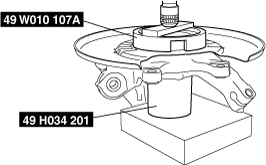
2. Align the marks on the new dust cover and rear knuckle.
3. Press the new dust cover onto the rear knuckle using the SSTs.
amxzzw00001252
|
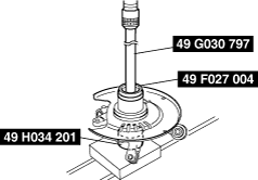
Wheel Bearing Installation Note
1. Install a new wheel bearing using the SSTs.
amxzzw00001253
|
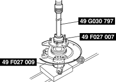
Wheel Hub Component Installation Note
1. Install the wheel hub component using the SSTs.
amxzzw00001254
|
Rear Knuckle Component Installation Note
1. Apply grease (D4Y0 33247) to the wheel bearing inner race and drive shaft contact surface (Area A in figure).
ardjjw00002360
|
2. Install the rear knuckle component.
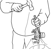
Locknut Installation Note
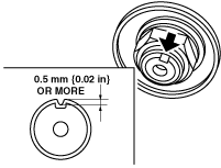
1. Tighten a new locknut.
2. Install a new locknut and indent as shown to crimp the locknut, using a chisel and hammer.
amxzzw00002426
|