 |
amxzzw00005851
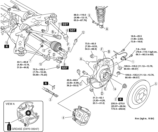
REAR DRIVE SHAFT REMOVAL/INSTALLATION
id031300800600
1. When working on the left side of the vehicle, disconnect the rear auto leveling sensor link. (Vehicle with discharge headlight system) (See REAR AUTO LEVELING SENSOR REMOVAL/INSTALLATION.)
2. Drain the rear differential oil.
3. Remove in the order indicated in the table.
4. Install in the reverse order of removal.
5. Add rear differential oil. (See DIFFERENTIAL OIL REPLACEMENT.)
amxzzw00005851
|
|
1
|
ABS wheel-speed sensor
|
|
2
|
Locknut
(See Locknut Removal Note.)
(See Locknut Installation Note.)
|
|
3
|
Parking brake cable
|
|
4
|
Brake caliper component
|
|
5
|
Disc plate
|
|
6
|
Rear lateral link (upper) ball joint
|
|
7
|
Stabilizer control link (lower)
|
|
8
|
Rear lateral link (lower) ball joint
|
|
9
|
Shock absorber bolt (lower)
|
|
10
|
Toe control link ball joint
|
|
11
|
Rear trailing link (upper) ball joint
|
|
12
|
Rear trailing link (lower) outside bolt
|
|
13
|
Rear knuckle component
|
|
14
|
Rear drive shaft
|
|
15
|
Clip
(See Clip Installation Note.)
|
Locknut Removal Note
1. Lock the disc plate by applying the brakes.
2. Knock the crimped portion of the locknut outward using a chisel and a hammer.
amxzzw00001256
|
3. Remove the locknut.
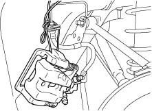
Brake Caliper Component Removal Note
1. Suspend the brake calliper component using a cable or equivalent.
amxzzw00001257
|
2. Temporarily tighten the wheel nut to prevent the disc plate from falling off.
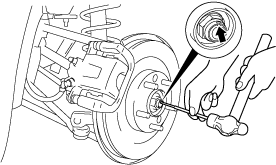
Rear Drive Shaft Removal Note
1. Temporarily install a spare nut to the end of the rear drive shaft.
2. Knock the nut with copper hammer lightly and remove the rear drive shaft from the wheel hub.
amxzzw00001258
|
3. Separate the rear drive shaft from the wheel hub.
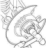
4. Insert a tire lever or equivalent between the rear differential and differential side outer ring, and then remove the rear drive shaft.
amxzzw00001259
|
5. Pull the rear drive shaft to the outer side of the vehicle and disconnect it from the rear differential.
6. To hold the rear knuckle component, install the rear lateral link (upper) to the rear knuckle temporarily after disconnecting the rear drive shaft.
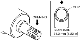
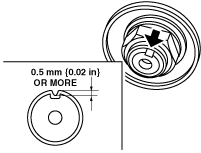
Clip Installation Note
1. Point the opening of the new drive shaft clip upward, install it to the clip groove at the end of the rear drive shaft with the installation width within the specification.
amxzzw00001260
|
2. After installing the clip, measure the outer diameter. If it exceeds the specification, reinstall the new clip.
Rear Drive Shaft Installation Note
1. Apply differential oil to the differential oil seal lip.
2. Insert the rear drive shaft into the rear differential with the clip opening facing upward.
3. After installation, verify that the rear drive shaft is securely held by the clip by pulling the outer ring on the differential side towards the axle.
Rear Knuckle Component Installation Note
1. Apply grease (D4Y0 33247) to the wheel bearing inner race and drive shaft contact surface (Area A in figure).
ardjjw00002360
|
2. Install the rear knuckle component.
Locknut Installation Note
1. Tighten a new locknut.
2. Crimp the locknut, using a chisel and hammer.
amxzzw00002371
|