 |
amxzzw00002310
REAR DIFFERENTIAL REMOVAL/INSTALLATION
id031400800400
1. Drain the rear differential oil.
2. Remove the insulator. (LF (MT)) (See TRANSMISSION REMOVAL/INSTALLATION [M15M-D].) (See TRANSMISSION REMOVAL/INSTALLATION [P66M-D].)
3. Remove the tunnel member. (MT) (See TRANSMISSION REMOVAL/INSTALLATION [M15M-D].) (See TRANSMISSION REMOVAL/INSTALLATION [P66M-D].)
4. Remove the tunnel member component. (AT) (See AUTOMATIC TRANSMISSION REMOVAL/INSTALLATION [SJ6A-EL].)
5. Remove the middle pipe. (See EXHAUST SYSTEM REMOVAL/INSTALLATION [L8, LF].)
6. Remove the propeller shaft. (See PROPELLER SHAFT REMOVAL/INSTALLATION.)
7. Disconnect the rear auto leveling sensor link. (Vehicle with discharge headlight system) (See REAR AUTO LEVELING SENSOR REMOVAL/INSTALLATION.)
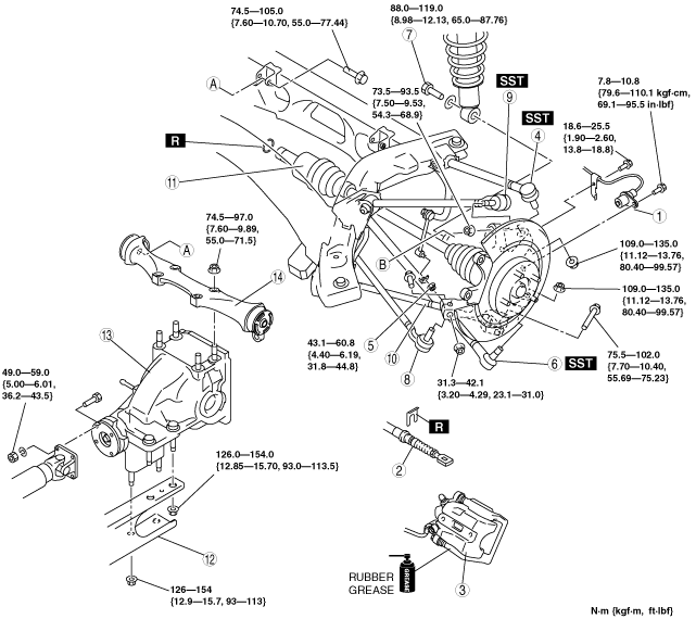
8. Remove in the order indicated in the table.
9. Install in the reverse order of removal.
10. Add rear differential oil. (See DIFFERENTIAL OIL REPLACEMENT.)
amxzzw00002310
|
|
1
|
ABS wheel-speed sensor
|
|
2
|
Parking brake cable
|
|
3
|
Brake caliper component
|
|
4
|
Rear lateral link (upper) ball joint
|
|
5
|
Stabilizer control link (lower)
|
|
6
|
Rear lateral link (lower) ball joint
|
|
7
|
Shock absorber bolt (lower)
|
|
8
|
Toe control link ball joint
|
|
9
|
Rear trailing link (upper) ball joint
|
|
10
|
Rear trailing link (lower)
|
|
11
|
Rear drive shaft, rear knuckle component
|
|
12
|
Power plant frame
|
|
13
|
Rear differential
|
|
14
|
Differential mount
|
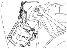
Brake Caliper Component Removal Note
1. Suspend the brake calliper component using a cable or equivalent.
amxzzw00002311
|
2. Temporarily tighten the wheel nut to prevent the disc plate from falling off.
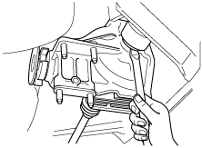
Rear Drive Shaft, Rear Knuckle Component Removal Note
1. Insert a tire lever or equivalent between the rear differential and differential side outer ring, and remove the rear drive shaft.
amxzzw00002312
|
2. Pull the rear drive shaft and rear knuckle component to the outer side, and detach the rear drive shaft from the rear differential.
3. To hold the rear drive shaft and rear knuckle component, install the rear lateral link (upper) to the rear knuckle temporarily after disconnecting the rear drive shaft.
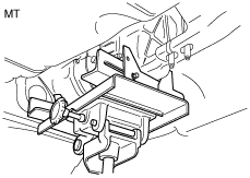
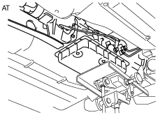
Power Plant Frame Removal Note
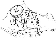
1. Support the transmission using a transmission jack.
amxzzw00002313
|
amxzzw00002382
|
2. Remove the power plant frame.
Rear Differential Removal Note
1. Remove the rear differential, while supporting it securely with a jack, and moving the jack gradually.
amxzzw00002383
|
Rear Differential, Power Plant Frame Installation Note
1. Support the rear differential using the jack.
amxzzw00002383
|
2. Temporarily tighten the differential mounting installation bolts.
3. Support the transmission and differential so that they are level using a transmission jack.
amxzzw00002313
|
amxzzw00002382
|
4. Install the power plant frame.
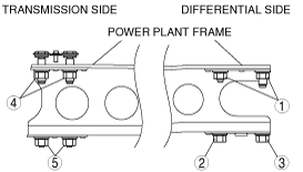
5. Temporarily tighten the nuts 1, 2, 3 in order shown in the figure.
amxzzw00002384
|
6. Tighten nut 2 until the power plant frame is seated in the rear differential.
7. Temporarily tighten the nuts 4, 5 in order shown in the figure.
8. Install the tunnel member (MT) or tunnel member component (AT). (See TRANSMISSION REMOVAL/INSTALLATION [M15M-D].) (See TRANSMISSION REMOVAL/INSTALLATION [P66M-D].) (See AUTOMATIC TRANSMISSION REMOVAL/INSTALLATION [SJ6A-EL].)
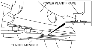
9. Raise the front end of the power plant frame (transmission side) or the transmission with the transmission jack, and adjust dimension A to 26.7—34.7 mm {1.06—1.36 in} (lower surface of power plant frame-upper surface of the tunnel member) as shown in the figure.
amxzzw00002385
|
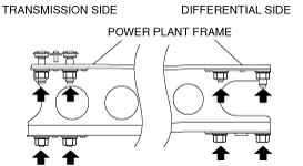
10. Tighten the power plant frame installation nuts.
amxzzw00002386
|
11. Verify that dimension A is within the specification with the transmission jack and the adjustment bolt removed.
12. Remove the tunnel member (MT) or tunnel member component (AT).
13. Temporarily loosen the differential mounting installation bolts, straighten the differential mounting bracket bushings, and then tighten the differential mounting installation bolts again to the specified torque.
Rear Drive Shaft, Rear Knuckle Component Installation Note
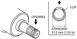
1. Install a new drive shaft clip to the clip groove at the top of the rear drive shaft with the clip opening facing upward and the clip width within the specification.
amxzzw00002315
|
2. After installing the clip, measure the outer diametric if it exceeds the specification, reinstall a new clip.
3. Apply differential oil to the differential oil seal lip.
4. Insert the rear drive shaft into the rear differential with the clip opening facing upward.
5. After installation, verify that the rear drive shaft is securely held by the clip by pulling the outer ring on the differential side towards the axle.