STEP
INSPECTION
ACTION
1
VERIFY WHETHER MALFUNCTION IS IN COMMON POWER SUPPLY OF WARNING LIGHTS AND INDICATOR LIGHTS, OR IN OTHER WARNING LIGHTS AND INDICATOR LIGHTS
• Verify other warning and indicator lights illuminate when the ignition switch is turned to the ON position?
• Is there any warning and indicator light?
Yes
Go to Step 4.
No
Go to the next step.
2
INSPECT INSTRUMENT CLUSTER POWER SUPPLY FUSE
• Inspect the instrument cluster power supply fuse.
• Is there any malfunction?
Yes
Inspect the blown fuse related wiring harness for short to ground.
Repair or replace the wiring harness for a possible short to ground, if necessary.
Install the appropriate amperage fuse.
No
Go to the next step.
*3
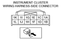
VERIFY WHETHER MALFUNCTION IS IN WIRING HARNESS (INSPECT FOR CONTINUITY BETWEEN INSTRUMENT CLUSTER POWER SUPPLY AND INSTRUMENT CLUSTER) OR INSTRUMENT CLUSTER
• Turn the ignition switch to the ON position (engine off).
• Measure the voltage at instrument cluster terminal 1G (wiring harness-side).
• Is the voltage approx. 12 V?
Yes
Replace the instrument cluster (open circuit in instrument cluster internal circuit).
No
Inspect the wiring harness between the instrument cluster and body ground for open circuit.
Repair or replace the wiring harness for a possible open circuit, if necessary.
4
CONFIRM DTC U1900
• Retrieve the DTC from the PCM, ABS and instrument cluster.
(See ON-BOARD DIAGNOSIS [ABS].)
• Is the DTC U1900 present?
Yes
Go to the next step.
No
Inspect the instrument cluster.
If the instrument cluster has a malfunction:
• Replace the instrument cluster.
If the instrument cluster is normal:
• Go to Step 6.
5
CONFIRM DTCS U0121, U0100 AND U0214
• Retrieve the DTC from the instrument cluster.
• Is the DTC U0121, U0100 or U0214 present?
Yes
Replace the instrument cluster (open circuit in instrument cluster).
No
Inspect the network communication for related system malfunction.
Repair or replace the malfunctioning part according to the inspection results, if necessary.
6
CONFIRM DTC B2477
• Retrieve the DTC from the instrument cluster.
• Is the DTC B2477 present?
Yes
Perform the instrument cluster configuration.
No
Replace the ABS HU/CM.