STEP
INSPECTION
ACTION
1
INSPECT ABS HU/CM POWER SUPPLY FUSE
• Turn the ignition switch off.
• Inspect the ABS HU/CM power supply fuse.
• Is there any malfunction?
Yes
Inspect the blown fuse related wiring harness for short to ground.
Repair or replace the wiring harness for a possible short to ground, if necessary.
Install the appropriate amperage fuse.
No
Go to the next step.
2
INSPECT WIRING HARNESS BETWEEN ABS HU/CM AND DLC‐2 FOR CONTINUITY AND SHORTS
• Perform the Reading DTCs Procedure.
(See ON-BOARD DIAGNOSIS [ABS].)
• Is the error message displayed regarding communication between ABS HU/CM and M-MDS?
Yes
If a communication error message is displayed even after inspecting according to the procedure displayed on the M-MDS, go to Step 10.
No
Go to the next step.
3
CONFIRM ABS HU/CM DTC
• Perform the Reading DTCs Procedure.
(See ON-BOARD DIAGNOSIS [ABS].)
• Are any DTC present?
Yes
Go to the applicable DTC inspection.
(See ON-BOARD DIAGNOSIS [ABS].)
No
Go to the next step.
4
INSPECT WARNING LIGHT OPERATION
• Turn on the all warning light on instrument cluster using the instrument cluster input/output check code 26.
• Do the ABS and brake system warning light illuminate?
Yes
Go to the next step.
No
Replace the instrument cluster.
5
INSPECT ABS HU/CM IGNITION POWER SUPPLY SYSTEM
• Perform the PID/Data Monitor and Record Procedure and access the ABS_VOLT PID.
(See ON-BOARD DIAGNOSIS [ABS].)
• Is the voltage within the specification?
Specification: approx. 10 V
Yes
Replace the ABS HU/CM (open or short circuit in ABS HU/CM internal ground circuit ).
No
Go to the next step.
6
INSPECT BATTERY
• Inspect the battery.
(See BATTERY INSPECTION [L8, LF].)
• Is there any malfunction?
Yes
Inspect the charging system.
Repair or replace the malfunctioning part according to the inspection results.
No
Go to the next step.
7
INSPECT CHARGING SYSTEM
• Start the engine.
• Measure the battery voltage with the electrical load (A/C, headlight, etc.) on and the engine idling.
• Is the voltage normal?
Yes
Go to the next step.
No
Inspect the charging system (drive belt tension, generator, etc.).
Repair or replace the malfunctioning part according to the inspection results.
*8
INSPECT ABS HU/CM POWER SUPPLY CIRCUIT FOR CONTINUITY
• Turn the ignition switch off.
• Disconnect the ABS HU/CM connector.
• Turn the ignition switch to the ON position (engine off).
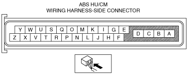
• Measure the voltage at ABS HU/CM terminal Z (wiring harness-side).
• Is the voltage approx. 12 V?
Yes
Go to the next step.
No
Inspect the ABS HU/CM connector for loose.
Reconnect the ABS HU/CM connector properly, if necessary.
*9
INSPECT ABS HU/CM GROUND CIRCUIT FOR CONTINUITY
• Turn the ignition switch off.
• Inspect for continuity between ABS HU/CM terminal D (wiring harness-side) and body ground.
• Is there continuity?
Yes
If a malfunction error message is displayed on the M-MDS in Step 1 inspection:
• Go to the next step.
If a malfunction error message is not displayed on the M-MDS in Step 1 inspection:
• Symptom troubleshooting is completed.
No
Repair or replace the wiring harness for a possible open circuit.
*10
INSPECT WIRING HARNESS BETWEEN ABS HU/CM AND DLC‐2 FOR CONTINUITY
• Turn the ignition switch off.
• Inspect for continuity between ABS HU/CM terminal Y, Z and DLC-2 (wiring harness-side).
• Is there continuity?
Yes
Go to the next step.
No
Repair or replace the wiring harness for a possible open circuit.
*11
INSPECT WIRING HARNESS BETWEEN ABS HU/CM AND DLC‐2 FOR SHORT TO POWER SUPPLY
• Turn the ignition switch to the ON position (engine off).
• Measure the voltage at ABS HU/CM terminal Y, Z (wiring harness-side).
• Is the voltage approx. 12 V?
Yes
Repair or replace the wiring harness for a possible short to power supply.
No
Go to the next step.
*12
INSPECT WIRING HARNESS BETWEEN ABS HU/CM AND DLC‐2 FOR SHORT TO GROUND
• Turn the ignition switch off.
• Inspect for continuity between ABS HU/CM terminal Y, Z (wiring harness-side) and body ground.
• Is there continuity?
Yes
Repair or replace the wiring harness for a possible short to ground.
No
Replace the ABS HU/CM (ABS HU/CM internal communication circuit malfunction).