|
1
|
VERIFY FREEZE FRAME DATA HAS BEEN RECORDED
• Has the FREEZE FRAME DATA been recorded on the repair order?
|
Yes
|
Go to the next step.
|
|
No
|
Record the FREEZE FRAME DATA on the repair order, then go to the next step.
|
|
2
|
VERIFY RELATED REPAIR INFORMATION AVAILABILITY
• Verify related service repair information availability.
• Is any related repair information available?
|
Yes
|
Perform repair or diagnosis according to the available repair information.
• If the vehicle is not repaired, go to the next step.
|
|
No
|
Go to the next step.
|
|
3
|
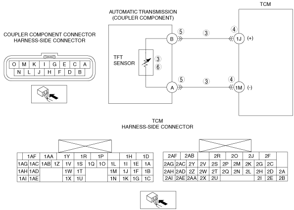
INSPECT RESISTANCE OF TFT SENSOR CIRCUIT
• Inspect for resistance between coupler component terminals 1J and 1M (wiring harness-side).
• Is resistance as shown below?
-
― ATF temperature 10°C {50°F}: approx. 6.445 kilohms
― ATF temperature 25°C {77°F}: approx. 3.5 kilohms
― ATF temperature 110°C {230°F}: approx. 0.247 kilohms
|
Yes
|
Go to the next step.
|
|
No
|
Go to Step 5.
|
|
4
|
INSPECT TCM CONNECTOR FOR POOR CONNECTION
• Turn the ignition switch to the LOCK position.
• Disconnect the TCM connector.
• Inspect for poor connection at TCM terminals 1J and 1M (such as damaged/pulled-out pins, corrosion).
• Are terminals normal?
|
Yes
|
Go to Step 7.
|
|
No
|
Repair or replace the connector and/or terminal, then go to Step 7.
|
|
5
|
INSPECT COUPLER COMPONENT CONNECTOR FOR POOR CONNECTION
• Disconnect the coupler component connector.
• Inspect for poor connection at TCM terminals A and B (such as damaged/pulled-out pins, corrosion).
• Are terminals normal?
|
Yes
|
Go to the next step.
|
|
No
|
Repair or replace the connector and/or terminal, then go to Step 7.
|
|
6
|
INSPECT TFT SENSOR
• Inspect the TFT sensor.
• Is the TFT sensor normal?
|
Yes
|
Repair or replace the wiring harness for open circuit, go to the next step.
|
|
No
|
Replace the TFT sensor, then go to the next step.
|
|
7
|
VERIFY TROUBLESHOOTING OF DTC P0713 COMPLETED
• Make sure to reconnect all the disconnected connectors.
• Clear the DTC using the M-MDS.
• Perform the following procedure to ensure that the DTC has been resolved:
-
1. Start the engine.
2. Warm-up the engine and transmission.
3. Drive the vehicle in D range and make sure that the gears shift smoothly from 1GR to 6GR.
• Is the same DTC present?
|
Yes
|
Replace the TCM, then go to the next step.
|
|
No
|
Go to the next step.
|
|
8
|
VERIFY NO DTC HAS BEEN PRESENTED
• Perform the “Reading DTCs Procedure”.
• Are any DTCs present?
|
Yes
|
Go to the applicable DTC inspection.
|
|
No
|
DTC troubleshooting completed.
|