 |
amxzzw00000986
ROAD TEST [SJ6A-EL]
id051311248900
Road Test Preparation
1. Inspect the engine coolant level. (See ENGINE COOLANT LEVEL INSPECTION [L8, LF].)
2. Inspect the engine oil level. (See ENGINE OIL LEVEL INSPECTION [L8, LF].)
3. Inspect the ATF level. (See AUTOMATIC TRANSMISSION FLUID (ATF) LEVEL ADJUSTMENT [SJ6A-EL].)
4. Inspect the idle speed. (See ENGINE TUNE-UP [L8, LF].)
5. Inspect the ignition timing. (See ENGINE TUNE-UP [L8, LF].)
6. Verify that no DTCs are stored.
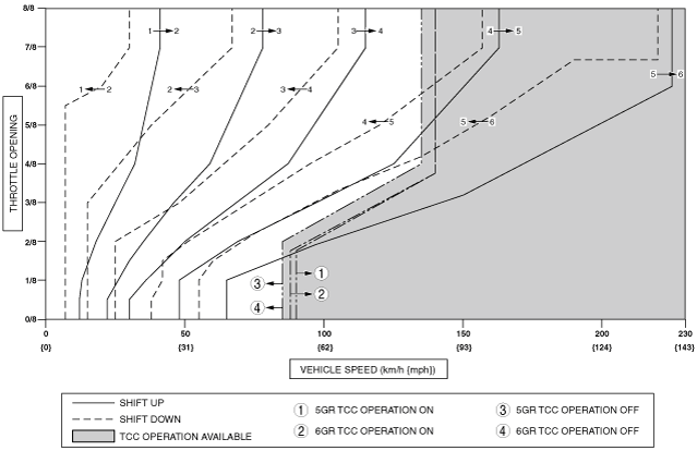
Shift Diagram
D range (normal mode)
amxzzw00000986
|
D Range Test
1. Perform road test preparation. (See Road Test Preparation.)
2. Shift the selector lever to the D range.
3. Accelerate with the throttle half and then wide open.
4. Verify that 1→2, 2→3, 3→4, 4→5, and 5→6 upshifts can be obtained. The shift points must be as shown in the table below.
5. Drive the vehicle in 6GR, 5GR, 4GR, 3GR, 2GR and verify that kickdown occurs for 6→5, 5→4, 4→3, 3→2, and 2→1 downshifts, and that the shift points are as shown in the table below.
6. Decelerate the vehicle and verify that engine braking effect is felt in 4GR, 5GR, and 6GR.
7. Drive the vehicle and verify that TCC operation is obtained. The operation points must be as shown in the table below.
Shift point table
|
Range |
Mode |
Throttle condition |
Shift |
Vehicle speed (km/h {mph}) |
Turbine speed (rpm) |
|---|---|---|---|---|---|
|
D
|
NORMAL
|
Wide open throttle
|
D1→D2
|
40—46 {25—28}
|
5,150—5,900
|
|
D2→D3
|
76—84 {48—52}
|
5,700—6,250
|
|||
|
D3→D4
|
112—122 {70—75}
|
5,750—6,200
|
|||
|
D4→D5
|
160—170 {100—105}
|
5,850—6,150
|
|||
|
TCC ON (D5)
|
160—170 {100—105}
|
4,150—4,400
|
|||
|
D5→D6
|
222—232 {138—143}
|
5,800—6,000
|
|||
|
TCC ON (D6)
|
222—232 {138—143}
|
4,700—4,900
|
|||
|
Half throttle
|
D1→D2
|
26—34 {17—21}
|
3,350—4,400
|
||
|
D2→D3
|
41—60 {26—37}
|
3,050—4,500
|
|||
|
D3→D4
|
70—95 {44—58}
|
3,600—4,850
|
|||
|
D4→D5
|
104—131 {65—81}
|
3,800—4,750
|
|||
|
TCC ON (D5)
|
130—150 {81—93}
|
3,350—3,900
|
|||
|
D5→D6
|
155—186 {97—115}
|
4,050—4,800
|
|||
|
TCC ON (D6)
|
155—186 {97—115}
|
3,300—3,950
|
|||
|
Closed throttle position
|
D6→D5
|
52—58 {33—35}
|
1,150—1,200
|
||
|
D5→D4
|
35—41 {22—25}
|
950—1,050
|
|||
|
D4→D3
|
23—29 {15—17}
|
850—1,050
|
|||
|
D3→D2
|
12—18 {8—11}
|
650—900
|
|||
|
D2→D1
|
4—10 {3—6}
|
300—700
|
|||
|
Kickdown
|
D6→D5
|
215—225 {134—139}
|
4,600—4,750
|
||
|
D5→D4
|
152—162 {95—100}
|
3,950—4,200
|
|||
|
D4→D3
|
100—110 {62—68}
|
3,650—4,000
|
|||
|
D3→D2
|
63—71 {40—44}
|
3,250—3,600
|
|||
|
D2→D1
|
27—33 {17—20}
|
2,050—2,450
|
|||
|
AAS
|
Wide open throttle
|
D1→D2
|
40—46 {25—28}
|
5,150—5,900
|
|
|
D2→D3
|
76—84 {48—52}
|
5,700—6,250
|
|||
|
D3→D4
|
112—122 {70—75}
|
5,750—6,200
|
|||
|
D4→D5
|
160—170 {100—105}
|
5,850—6,150
|
|||
|
TCC ON (D5)
|
160—170 {100—105}
|
4,150—4,400
|
|||
|
D5→D6
|
222—232 {138—143}
|
5,800—6,000
|
|||
|
TCC ON (D6)
|
222—232 {138—143}
|
4,700—4,900
|
|||
|
Half throttle
|
D1→D2
|
26—34{17—21}
|
3,350—4,400
|
||
|
D2→D3
|
48—64 {30—39}
|
3,600—4,800
|
|||
|
D3→D4
|
71—94 {45—58}
|
3,600—4,800
|
|||
|
D4→D5
|
104—131 {65—81}
|
3,800—4,750
|
|||
|
TCC ON (D5)
|
130—150 {81—93}
|
3,350—3,900
|
|||
|
D5→D6
|
216—234 {134—145}
|
5,650—6,050
|
|||
|
TCC ON (D6)
|
216—234 {134—145}
|
4,600—4,950
|
|||
|
Closed throttle position
|
D6→D5
|
52—58 {33—35}
|
1,150—1,200
|
||
|
D5→D4
|
35—41 {22—25}
|
950—1,050
|
|||
|
D4→D3
|
22—28 {14—17}
|
850—1,000
|
|||
|
D3→D2
|
12—18 {8—11}
|
650—900
|
|||
|
D2→D1
|
4—10 {3—6}
|
300—700
|
|||
|
Kickdown
|
D6→D5
|
215—225 {134—139}
|
4,600—4,750
|
||
|
D5→D4
|
152—162 {95—100}
|
3,950—4,200
|
|||
|
D4→D3
|
100—110 {62—68}
|
3,650—4,000
|
|||
|
D3→D2
|
63—71 {40—44}
|
3,250—3,600
|
|||
|
D2→D1
|
27—33 {17—20}
|
2,050—2,450
|
Direct Mode Test
1. Perform road test preparation. (See Road Test Preparation.)
2. Shift the selector lever to D range.
3. Perform the following tests.
|
Driving conditions |
Inspection item |
||||
|---|---|---|---|---|---|
|
Range |
Mode |
Gear position |
Accelerator opening angle (%) |
Vehicle speed (km/h {mph}) |
|
|
D
|
Automatic shift mode
|
3GR
|
10—15
|
35—45 {22—27}
|
• While driving under condition indicated on left with up-switch of steering shift switch operated, verify shift-up to 4GR with system switched to direct mode.
|
|
D
|
Automatic shift mode
|
4GR
|
10—15
|
35—45 {22—27}
|
• While driving under condition indicated on left with down-switch of steering shift switch operated, verify shift-down to 3GR with system switched to direct mode.
|
|
Driving conditions |
Inspection item |
||||
|---|---|---|---|---|---|
|
Range |
Mode |
Gear position |
Accelerator opening angle (%) |
Vehicle speed (km/h {mph}) |
|
|
D
|
Direct mode
|
4GR
|
10—15
|
35—45 {22—27}
|
• While driving under condition indicated on left and at constant speed for several seconds *, verify that system switches to automatic shift mode automatically.
|
M Range Test
1. Perform road test preparation. (See Road Test Preparation.)
2. Shift the selector lever to M range.
3. Verify that 1→2, 2→3, 3→4, 4→5, and 5→6 upshifts and 6→5, 5→4, 4→3, 3→2, and 2→1 downshifts are obtained by manual shifting.
4. Decelerate the vehicle and verify that 6→5, 5→4, 4→3, 3→2, and 2→1 downshifts are obtained. The shift points must be as shown in the table below.
5. Decelerate the vehicle and verify that engine braking effect is felt in all gears.
6. Drive the vehicle and verify that TCC operation is obtained in 5GR and 6GR. The operation points must be as shown in the table below.
Vehicle speed at shift point table
|
Range |
Mode |
Throttle condition |
Shift |
Vehicle speed km/h {mph} |
Turbine speed (rpm) |
|---|---|---|---|---|---|
|
M
|
Normal
|
Half throttle
|
TCC ON (D5)
|
130—150 {81—93}
|
3,350—3,900
|
|
TCC ON (D6)
|
130—150 {81—93}
|
2,750—3,200
|
|||
|
All round
|
D6→D5
|
44—50 {28—31}
|
950—1,050
|
||
|
D5→D4
|
35—41 {22—25}
|
950—1,050
|
|||
|
D4→D3
|
17—23 {11—14}
|
650—800
|
|||
|
D3→D2
|
12—18 {8—11}
|
650—900
|
|||
|
D2→D1
|
9—15 {6—9}
|
700—1,100
|
P Position Test
1. Shift into the P position on a gentle slope. Release the brake, and verify that the vehicle does not roll.