 |
amxzzw00001468
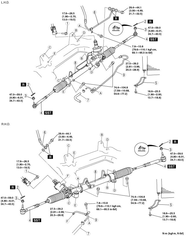
STEERING GEAR AND LINKAGE REMOVAL/INSTALLATION
id061400800900
1. Remove the ABS wheel-speed sensor. (See FRONT ABS WHEEL-SPEED SENSOR REMOVAL/INSTALLATION.)
2. Remove the splash shield A. (See SPLASH SHIELD REMOVAL/INSTALLATION.)
3. Remove the front under cover. (See FRONT UNDER COVER REMOVAL/INSTALLATION.)
4. Remove the front stabilizer. (See FRONT STABILIZER REMOVAL/INSTALLATION.)
5. Remove in the order indicated in the table.
6. Install in the reverse order of removal.
7. After installation, adjust front wheel alignment. (See FRONT WHEEL ALIGNMENT.)
amxzzw00001468
|
|
1
|
Bolt (intermediate shaft)
|
|
2
|
Cotter pin
|
|
3
|
Nuts (tie-rod end ball joint)
|
|
4
|
Tie-rod end ball joint
|
|
5
|
Radiator lower mount rubber bracket
|
|
6
|
Pressure pipe
|
|
7
|
Return hose
|
|
8
|
Steering gear and linkage
|
|
9
|
Return pipe
|
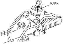
Bolt (Intermediate Shaft) Removal Note
1. Mark the pinion shaft and gear housing for proper installation.
amxzzw00001469
|
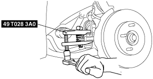
Tie-rod End Ball Joint Removal Note
1. Remove the tie-rod nut.
2. Separate the tie-rod end from the steering knuckle using the SSTs.
amxzzw00001470
|
Steering Gear and Linkage Removal Note
1. Remove the steering gear and linkage by pulling it from the right side.
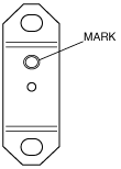
Steering Gear and Linkage Installation Note
1. Tighten bolts loosely.
2. Assemble the mounting bracket with the mark on the bracket facing the vehicle rear.
amxzzw00001471
|
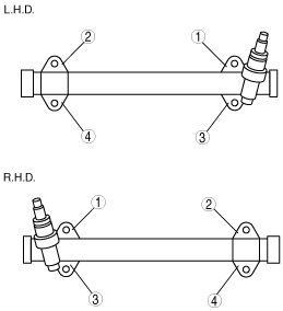
3. Tighten the mounting bracket bolts to the specified torque in the order shown.
amxzzw00001472
|
Bolt (Intermediate Shaft) Installation Note
1. Align the marks and install the intermediate shaft and bolt.