|
amxzzw00003436
EXHAUST SYSTEM REMOVAL/INSTALLATION [SKYACTIV-G 1.5, SKYACTIV-G 2.0]
id0115zh800200
1. Disconnect the negative battery terminal. (See NEGATIVE BATTERY TERMINAL DISCONNECTION/CONNECTION.)
2. Remove in the order indicated in the table.
3. Remove the exhaust system insulator. (See Exhaust System Insulator Removal/Installation.)
4. Install in the reverse order of removal.
Step 1
amxzzw00003436
|
|
1
|
Main silencer
|
|
2
|
Seal ring
(See Seal Ring Removal Note.)
(See Seal Ring Installation Note.)
|
|
3
|
HO2S
|
|
4
|
Center under cover (with center under cover)
|
|
5
|
Tunnel member
|
|
6
|
Plate (with plate)
(See PLATE REMOVAL/INSTALLATION.)
|
|
7
|
Member bracket (with member bracket)
|
|
8
|
TWC
|
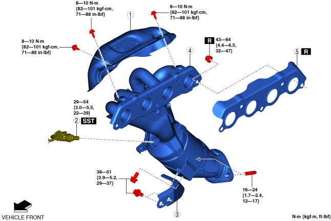
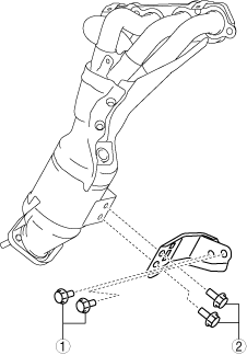
Step 2 (SKYACTIV-G 1.5)
amxzzw00003437
|
|
1
|
Exhaust manifold insulator
|
|
2
|
A/F sensor
|
|
3
|
Bracket
(See Bracket Installation Note.)
|
|
4
|
Exhaust manifold (WU-TWC)
|
|
5
|
Gasket
|
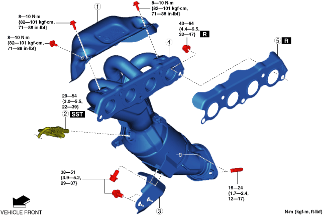
Step 2 (SKYACTIV-G 2.0)
amxuuw00005220
|
|
1
|
Exhaust manifold insulator
|
|
2
|
A/F sensor
|
|
3
|
Bracket
(See Bracket Installation Note.)
|
|
4
|
Exhaust manifold (WU-TWC)
|
|
5
|
Gasket
|
Exhaust System Insulator Removal/Installation
1. Remove the shift.
2. Remove the propeller shaft. (See PROPELLER SHAFT REMOVAL/INSTALLATION.)
3. Remove the power plant frame. (See POWER PLANT FRAME REMOVAL/INSTALLATION [SJ6A-EL].) (See POWER PLANT FRAME REMOVAL [M66M-D].) (See POWER PLANT FRAME INSTALLATION [M66M-D].)
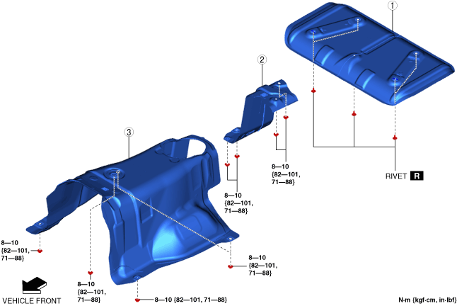
4. Remove the exhaust system insulator in the order shown in the figure.
5. Install in the reverse order of removal.
amxzzw00005757
|
|
1
|
Insulator (rear)
|
|
2
|
Insulator (middle)
|
|
3
|
Insulator (front)
|
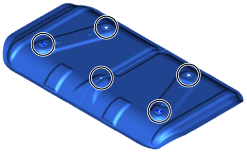
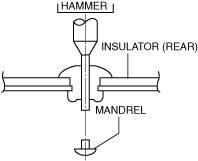
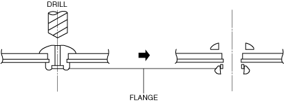
Insulator (rear) removal note
1. Remove the rivets as shown in the figure.
amxuuw00005222
|
amxuuw00005223
|
amxuuw00005224
|
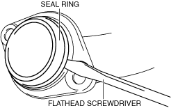
Seal Ring Removal Note
1. Remove the seal ring using a flathead screwdriver being careful not to damage the pipe.
amxuuw00005225
|
Exhaust Manifold Insulator Removal Note
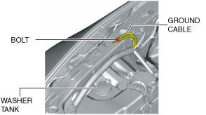
Exhaust Manifold Removal Note
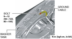
1. Remove the bolt shown in the figure and set the ground cable aside.
amxuuw00005226
|
2. Remove the front suspension tower bar (joint) and front suspension tower bar (RH) (with front suspension tower bar) (See FRONT SUSPENSION TOWER BAR REMOVAL/INSTALLATION.)
3. Remove the front wheels and tires. (See GENERAL PROCEDURES (SUSPENSION).)
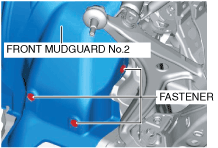
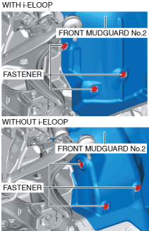
4. Remove the fasteners shown in the figure and slightly bend back the front mudguard No.2.
RH
amxuuw00005227
|
LH
amxzzw00003438
|
5. Remove the front splash shield No.1. (See FRONT SPLASH SHIELD No.1 REMOVAL/INSTALLATION.)
6. Remove the front crossmember under cover. (See FRONT CROSSMEMBER UNDER COVER REMOVAL/INSTALLATION.)
7. Remove the intermediate shaft. (R.H.D.) (See INTERMEDIATE SHAFT REMOVAL/INSTALLATION.)
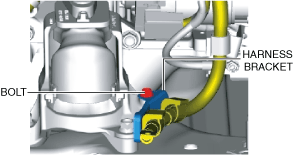
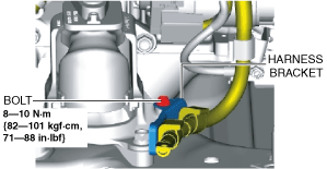
8. Remove the bolt shown in the figure and set the harness bracket aside. (with i-ELOOP)
amxzzw00003439
|
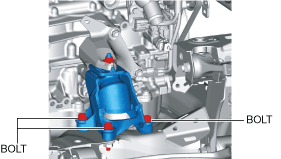
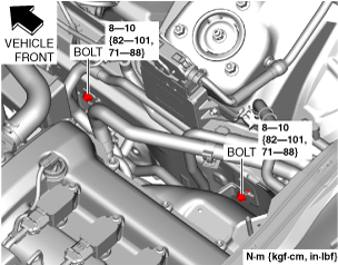
9. Remove the bolts shown in the figure.
RH
amxuuw00005229
|
LH
amxuuw00005230
|
10. Disconnect the service plug.(See SERVICE PLUG DISCONNECTION/CONNECTION [i-ELOOP].)
11. Remove the DC-DC converter (i-ELOOP). (with i-ELOOP) (L.H.D.) (See DC-DC CONVERTER (i-ELOOP) REMOVAL/INSTALLATION [i-ELOOP].)
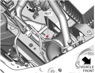
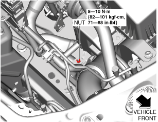
12. Remove the nut shown in the figure. (L.H.D.)
amxzzw00003440
|
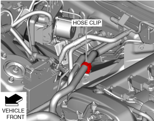
13. Disconnect the hose clip shown in the figure. (L.H.D.)
amxzzw00003441
|
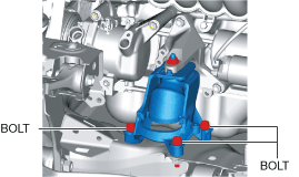
14. Remove the bolts shown in the figure. (L.H.D.)
amxzzw00003442
|
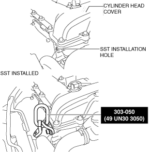
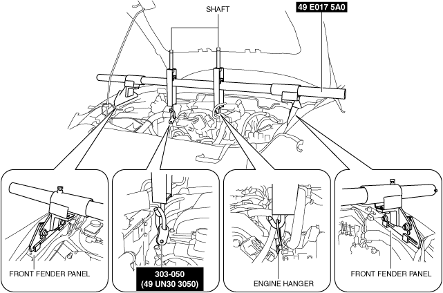
15. Install the SST to the position shown in the figure using the following bolt.
amxuuw00005231
|
16. Install the SST (49 E017 5A0) to the SST (49 UN30 3050) and engine hanger, then set them as shown in the figure.
amxuuw00005232
|
17. Rotate the shaft of the SST (49 E017 5A0) to support the engine.
18. Lift up the engine until the engine mount rubber is slightly raised above the front crossmember and verify again that the engine is securely hung.
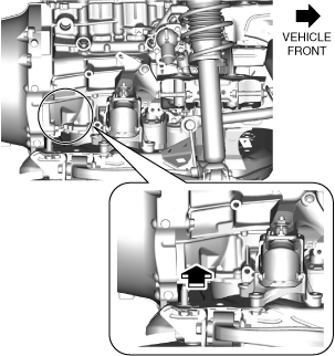
19. Push the engine as shown in the figure.
amxuuw00005233
|
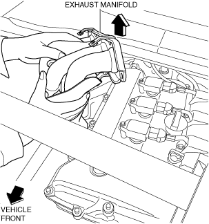
20. Remove the exhaust manifold.
amxuuw00005234
|
Exhaust Manifold Installation Note
1. Push the engine as shown in the figure.
amxuuw00005233
|
2. Install the exhaust manifold.
amxzzw00003443
|
3. Turn a shaft of SST (49 E017 5A0) and lower engine until engine mount rubber performs a sitting lightly in front crossmember.
4. Temporarily tighten the bolt as shown in the figure.
RH
amxuuw00005229
|
LH
amxuuw00005230
|
5. Turn a shaft of SST (49 E017 5A0) and lower engine more.
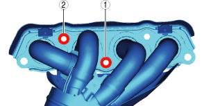
6. Tighten the bolt as shown in the figure.
RH
amxuuw00005235
|
LH
amxuuw00005236
|
7. Remove the SST (49 E017 5A0) and SST (49 UN30 3050).
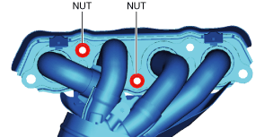
8. Temporarily tighten the nut as shown in the figure.
amxzzw00003444
|
9. Tighten the nut and as shown in the figure.
amxuuw00005237
|
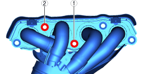
10. Temporarily tighten the nut as shown in the figure.
amxzzw00003445
|
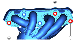
11. Tighten the nut to as shown in the figure.
amxuuw00005238
|
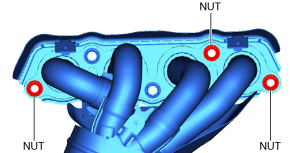
12. Tighten the nut as shown in the figure.
amxuuw00005239
|
13. Tighten the bolts shown in the figure. (L.H.D.)
amxzzw00003446
|
14. Connect the hose clip shown in the figure. (L.H.D.)
amxzzw00003441
|
15. Tighten the nut shown in the figure. (L.H.D.)
amxzzw00003447
|
16. Install the DC-DC converter (i-ELOOP). (with i-ELOOP) (L.H.D.) (See DC-DC CONVERTER (i-ELOOP) REMOVAL/INSTALLATION [i-ELOOP].)
17. Connect the service plug.(See SERVICE PLUG DISCONNECTION/CONNECTION [i-ELOOP].)
18. Install the harness bracket as shown in the figure. (with i-ELOOP)
amxzzw00003448
|
19. Install the intermediate shaft. (R.H.D.) (See INTERMEDIATE SHAFT REMOVAL/INSTALLATION.)
20. Install the front crossmember under cover. (See FRONT CROSSMEMBER UNDER COVER REMOVAL/INSTALLATION.)
21. Install the front splash shield No.1. (See FRONT SPLASH SHIELD No.1 REMOVAL/INSTALLATION.)
22. Install the front mudguard No.2. (See FRONT MUDGUARD REMOVAL/INSTALLATION.)
23. Install the front wheels and tires. (See GENERAL PROCEDURES (SUSPENSION).)
24. Install the front suspension tower bar (joint) and front suspension tower bar (RH). (with front suspension tower bar) (See FRONT SUSPENSION TOWER BAR REMOVAL/INSTALLATION.)
25. Install the ground cable shown in the figure.
amxuuw00005240
|
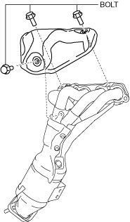
Bracket Installation Note
1. Temporarily tighten the bolt as shown in the figure.
amxzzw00003449
|
2. Tighten the bolt as shown in the figure.
amxzzw00003449
|
Exhaust Manifold Insulator Installation Note
1. Install the exhaust manifold insulator.
2. Temporarily tighten the bolt as shown in the figure.
amxzzw00003450
|
3. Tighten the bolt as shown in the figure.
amxzzw00003450
|
4. Check that there is no contact with an exhaust manifold and exhaust manifold insulator.
Flange Surface Installation Note
1. Sand the surface shown in the figure using sandpaper and remove sanding residue, accumulated matter, and friction marks.
2. Degrease the sanded surface.
amxuuw00005241
|
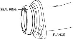
Seal Ring Installation Note
1. Temporarily install the seal ring to the pipe so that the seal ring is even with the flange.
amxuuw00005242
|
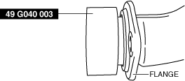
2. Install the SST to the seal ring so that the SST is even with the flange.
amxuuw00005243
|
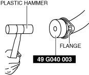
3. Press in the seal ring by tapping the SST using a plastic hammer until the seal ring contacts the flange.
amxuuw00005244
|