amxzzw00003817
|
PCM REMOVAL/INSTALLATION [SKYACTIV-G 1.5, SKYACTIV-G 2.0]
id0140g8802400
Without Set Bolt
1. Disconnect the negative battery cable. (See NEGATIVE BATTERY TERMINAL DISCONNECTION/CONNECTION.)
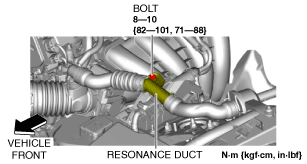
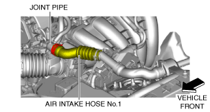
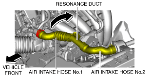
2. Set the resonance duct and air intake hoses No.1 and 2 aside as a single unit using the following procedure. (With resonance chamber No.2)
amxzzw00003817
|
amxzzw00003818
|
amxzzw00003819
|
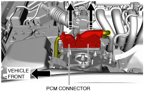
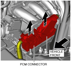
3. Disconnect the PCM connector. (See PCM Connector Connection Note.)
amxuuw00003657
|
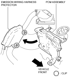
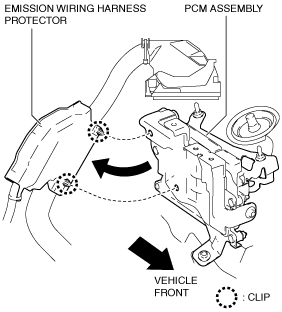
4. Detach the clips and remove the emission wiring harness protector.
amxuuw00003658
|
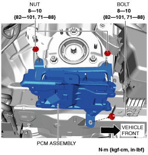
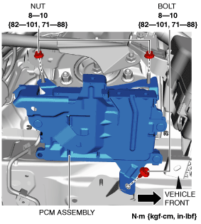
5. Remove the nuts and bolt.
amxuuw00003659
|
6. Remove the PCM assembly.
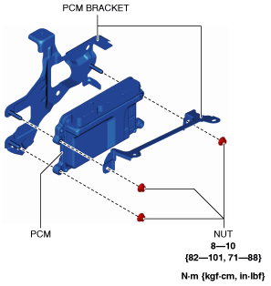
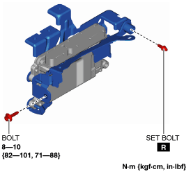
7. Remove the nuts.
amxuuw00003660
|
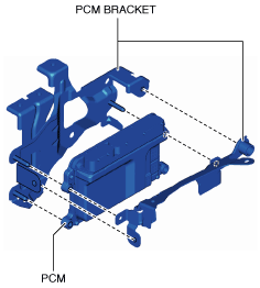
8. Remove the PCM from the PCM bracket.
9. Install in the reverse order of removal.
10. When replacing the PCM on the vehicles, perform the following:
With Set Bolt
1. Disconnect the negative battery cable. (See NEGATIVE BATTERY TERMINAL DISCONNECTION/CONNECTION.)
2. Set the resonance duct and air intake hoses No.1 and 2 aside as a single unit using the following procedure. (With resonance chamber No.2)
amxzzw00003817
|
amxzzw00003818
|
amxzzw00003819
|
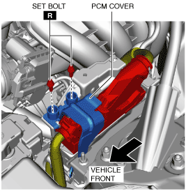
3. Remove the PCM cover. (See Set bolt removal note.) (See Set bolt installation note.) (See PCM cover installation note.)
amxzzw00002942
|
4. Disconnect the PCM connector. (See PCM Connector Connection Note.)
amxzzw00002943
|
5. Detach the clips and remove the emission wiring harness protector.
amxzzw00002944
|
6. Remove the nuts and bolt.
amxzzw00002945
|
7. Remove the PCM assembly.
8. Remove the nuts.
amxzzw00002946
|
9. Remove the bolt and set bolt. (See Set bolt removal note.) (See Set bolt installation note.)
amxzzw00002947
|
10. Remove the PCM from the PCM bracket.
amxzzw00002948
|
11. Install in the reverse order of removal.
12. When replacing the PCM on the vehicles, perform the following:
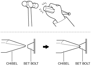
Set bolt removal note
1. Using a chisel and a hammer, cut a groove on the head of the set bolt so that a screwdriver can be inserted.
2. Loose the set bolt using an impact screwdriver or pliers.
am6zzw00010938
|
Set bolt installation note
1. Install a new set bolt and tighten it until the neck of the bolt breaks off.
amxzzw00002949
|
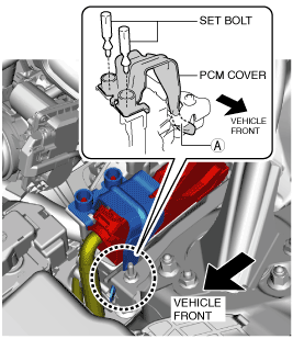
PCM cover installation note
1. Insert the PCM cover end into area A shown in the figure.
amxzzw00002950
|
2. Temporarily tighten the two set bolts, then completely tighten them.
PCM Connector Connection Note
amxuuw00003661
|
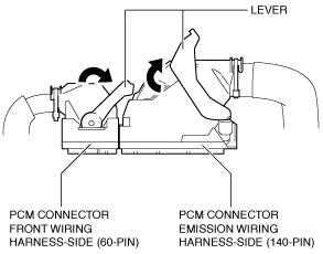
1. Set the PCM connector to the position shown in the figure.
amxuuw00003662
|
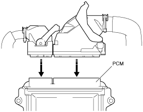
2. Align the PCM connector straight against the connection surface.
amxuuw00003663
|
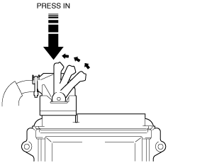
3. Insert the PCM connector straight and press it in until the lever moves up naturally. (Front wiring harness-side connector)
amxuuw00003664
|
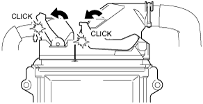
4. Press the PCM connector lever until a click sound is heard.
amxuuw00003665
|