 |
amxuuw00005361
REAR CROSSMEMBER REMOVAL/INSTALLATION
id021400204033
1. Disconnect the negative battery terminal. (See NEGATIVE BATTERY TERMINAL DISCONNECTION/CONNECTION.)
2. Drain the differential oil. (See DIFFERENTIAL OIL REPLACEMENT.)
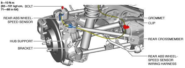
3. Remove the rear ABS wheel-speed sensor from the hub support.
amxuuw00005361
|
4. Remove the grommet and clip of the rear ABS wheel-speed sensor wiring harness from the bracket and rear crossmember and set it aside so that it does not interfere with the servicing.
5. Remove the rear the rear stabilizer component and the rear stabilizer control link as a single unit. (With rear stabilizer) (See REAR STABILIZER REMOVAL/INSTALLATION.)
6. Remove the floor under cover. (See FLOOR UNDER COVER REMOVAL/INSTALLATION.)
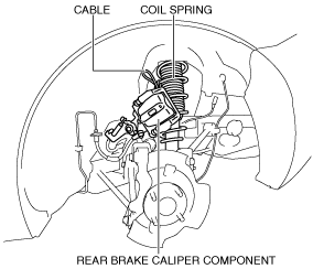
7. Remove the rear parking cable bracket from the rear crossmember. (See REAR PARKING BRAKE CABLE REMOVAL/INSTALLATION.)
8. Remove the rear brake caliper component and hang it in a place out of the way using a cable. (See REAR BRAKE DISC REMOVAL/INSTALLATION.)
amxuuw00003439
|
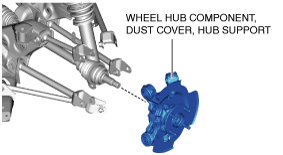
9. Remove the rear disc plate. (See REAR BRAKE DISC REMOVAL/INSTALLATION.)
10. Disconnect the following parts from the hub support and remove the wheel hub component, dust cover, and hub support as a single unit. (See WHEEL HUB COMPONENT REMOVAL/INSTALLATION.)
amxuuw00005362
|
11. Remove the plate. (With plate) (See PLATE REMOVAL/INSTALLATION.)
12. Remove the center under cover. (With center under cover) (See CENTER UNDER COVER REMOVAL/INSTALLATION.)
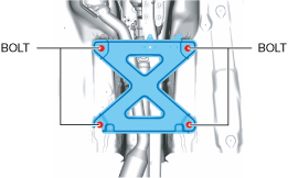
13. Remove the bolts.
amxuuw00005363
|
14. Remove the member bracket. (With member bracket)
15. Remove the bolts.
amxuuw00005364
|
16. Remove the tunnel member.
17. Remove the three way catalytic converter (TWC). (See EXHAUST SYSTEM REMOVAL/INSTALLATION [SKYACTIV-G 1.5, SKYACTIV-G 2.0].) (See TWC Installation Note.)
18. Remove the propeller shaft. (See PROPELLER SHAFT REMOVAL/INSTALLATION.)
19. Remove the power plant frame. (See POWER PLANT FRAME REMOVAL [M66M-D].) (See POWER PLANT FRAME INSTALLATION [M66M-D].)
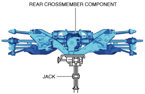
20. Support the rear crossmember component using a jack.
amxuuw00003440
|
21. Remove the nuts.
amxuuw00003441
|
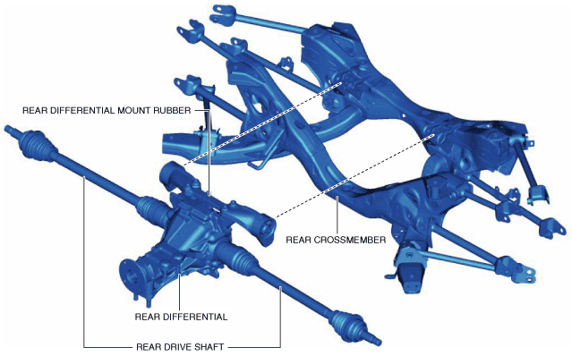
22. Lower the jack slowly and remove the rear crossmember component.
23. Remove the rear differential mount rubber securing bolt from the rear crossmember. (See REAR DIFFERENTIAL MOUNT RUBBER REMOVAL/INSTALLATION. )
24. Remove the rear differential, rear differential mount rubber and rear drive shaft from the rear crossmember.
amxuuw00003442
|
25. Remove the following parts from the rear crossmember.
26. Install in the reverse order of removal.
27. Add differential oil. (See DIFFERENTIAL OIL REPLACEMENT.)
28. Inspect the rear wheel alignment and adjust if necessary. (See REAR WHEEL ALIGNMENT.)
TWC Installation Note
1. Remove the tunnel member temporarily.
amxuuw00005365
|
2. Install the TWC. (See EXHAUST SYSTEM REMOVAL/INSTALLATION [SKYACTIV-G 1.5, SKYACTIV-G 2.0].)