 |
amxuuw00003585
SHIFT-LOCK SYSTEM INSPECTION
id051400260400
Shift-Lock System Inspection
1. Switch the ignition ON (engine off).
2. Shift the selector lever to the P position.
3. Verify that lock release button cannot be pressed in and the selector lever cannot be shifted from the P to R position when the brake pedal is not depressed.
4. Verify that the selector lever can be shifted from P to R position while the lock release button is pressed with brake pedal depressed.
Shift-Lock Solenoid Inspection
1. Disconnect the negative battery terminal. (See NEGATIVE BATTERY TERMINAL DISCONNECTION/CONNECTION.)
2. Remove the following parts:
3. Reconnect the negative battery terminal. (See NEGATIVE BATTERY TERMINAL DISCONNECTION/CONNECTION.)
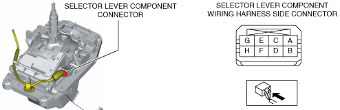
4. Verify that the voltages of each of the selector lever component terminals are as indicated in the table.
amxuuw00003585
|
Shift-lock solenoid specification
|
Terminal |
Connected to |
Test condition |
Voltage (V) |
|
|---|---|---|---|---|
|
A
|
IG1 relay
|
Ignition switched ON (engine on)
|
B+
|
|
|
Except above
|
Below 1.0
|
|||
|
F
|
Start stop unit
|
Ignition switched ON (engine on)
|
Selector lever at P position and brake pedal depressed
|
Below 1.0
|
|
Except above
|
B+
|
|||
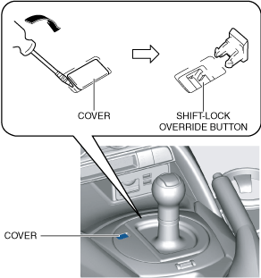
Shift-lock Override Button Inspection
1. Switch the ignition off.
2. Verify that the selector lever is in the P position.
3. Without the brake pedal depressed, verify that the selector lever cannot be shifted from the P position.
4. Perform the following procedure for vehicles with shift-lock override cover.
amxuuw00003586
|
5. Perform the following procedure for vehicles without shift-lock override cover.
amxzzw00003363
|
6. Verify that the selector lever can be shifted from the P position.