amxzzw00004479
|
AUTOMATIC TRANSMISSION SHIFT MECHANISM REMOVAL/INSTALLATION
id051400260200
Selector Lever Component Removal/Installation
1. Disconnect the negative battery terminal. (See NEGATIVE BATTERY TERMINAL DISCONNECTION/CONNECTION.)
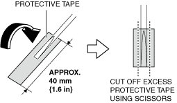
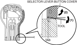
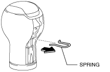
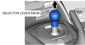
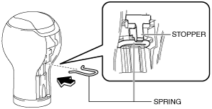
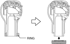
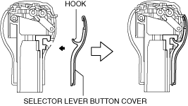
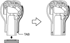
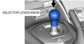
2. Perform the following procedure to remove the selector lever knob.
amxzzw00004479
|
amxzzw00004076
|
amxzzw00004077
|
amxuuw00003574
|
amxzzw00004480
|
3. Remove the following parts:
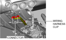
4. Disconnect the connector and wiring harness clip.
amxuuw00002845
|
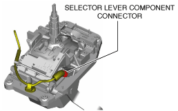
5. Disconnect the selector lever component connector.
amxuuw00002843
|
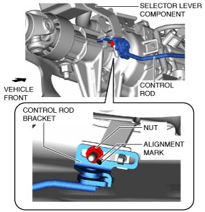
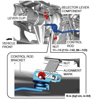
6. Place alignment marks on the control rod bracket and nut.
amxuuw00003576
|
7. Remove the nut.
amxuuw00003577
|
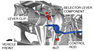
8. Disconnect the control rod from the lever clip of the selector lever component.
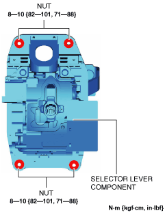
9. Remove the nuts from the selector lever component.
amxuuw00003578
|
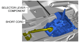
10. Set the short cord aside and remove the selector lever component.
amxuuw00003579
|
11. Pass the short cord through the installation hole and install the selector lever component.
12. Install the nuts to the selector lever component.
amxuuw00003578
|
13. Assemble the control rod to the lever clip of the selector lever component.
amxuuw00003580
|
14. Align the alignment marks on the control rod bracket and nut, and install the nut.
15. Connect the selector lever component connector.
amxuuw00002843
|
16. Connect the connector and wiring harness clip.
amxuuw00002845
|
17. Install the following parts:
18. Perform the following procedure to install the selector lever knob.
amxuuw00003581
|
amxzzw00004078
|
amxzzw00004079
|
amxzzw00004080
|
amxzzw00004481
|
19. Connect the negative battery terminal. (See NEGATIVE BATTERY TERMINAL DISCONNECTION/CONNECTION.)
Control Rod Removal/Installation
1. Disconnect the negative battery terminal. (See NEGATIVE BATTERY TERMINAL DISCONNECTION/CONNECTION.)
2. Remove the following parts:
3. Disconnect the connector and wiring harness clip.
amxuuw00002845
|
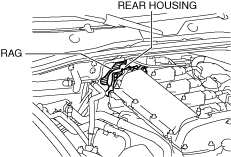
4. Place a clean rag behind the engine so that the engine does not contact the rear housing when it is tilted.
amxzzw00005089
|
5. Remove the front crossmember under cover. (See FRONT CROSSMEMBER UNDER COVER REMOVAL/INSTALLATION.)
6. Disconnect the control rod from the selector lever component. (See Selector Lever Component Removal/Installation.)
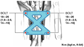
7. Remove the tunnel member.
amxuuw00003818
|
8. Disconnect the HO2S connector. (See HEATED OXYGEN SENSOR (HO2S) REMOVAL/INSTALLATION [SKYACTIV-G 1.5, SKYACTIV-G 2.0].)
9. Disconnect the TWC from the exhaust manifold (WU-TWC). (See EXHAUST SYSTEM REMOVAL/INSTALLATION [SKYACTIV-G 1.5, SKYACTIV-G 2.0].) (See TWC installation note.)
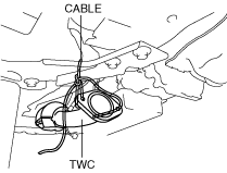
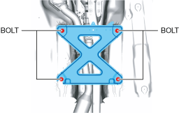
10. Suspend the TWC using a cable as shown in the figure.
amxuuw00002847
|
11. Remove the power plant frame. (See POWER PLANT FRAME REMOVAL [M66M-D].) (See POWER PLANT FRAME INSTALLATION [M66M-D].)
12. Tilt the transmission while being careful not to allow parts on the back of the engine to contact the vehicle body.
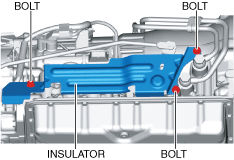
13. Remove the insulator. (See Insulator installation note.)
amxuuw00002848
|
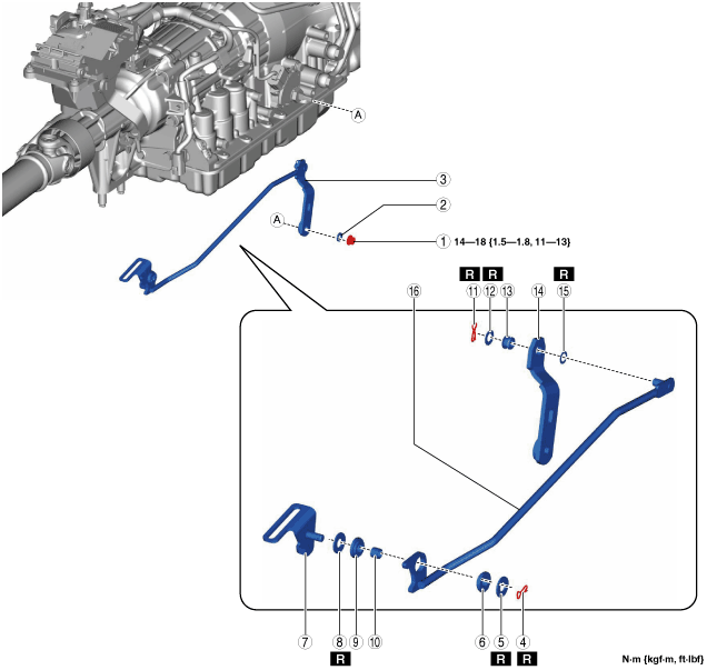
14. Remove in the order indicated in the table.
15. Install in the reverse order of removal.
amxuuw00003583
|
|
1
|
Nut
|
|
2
|
Washer
|
|
3
|
Control rod component
|
|
4
|
Snap pin
|
|
5
|
Washer
|
|
6
|
Bush
|
|
7
|
Bracket
|
|
8
|
Washer
|
|
9
|
Bush
|
|
10
|
Spacer
|
|
11
|
Snap pin
|
|
12
|
Washer
|
|
13
|
Bush
|
|
14
|
Bracket
|
|
15
|
Wave washer
|
|
16
|
Control rod
|
Nut, washer and control rod component removal note
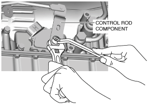
1. Secure the control rod component with an adjustable wrench as shown in the figure.
amxuuw00002850
|
2. Remove the control rod nut.
amxuuw00002851
|
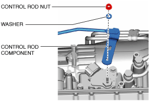
3. Remove the washer and control rod component.
Control rod component, nut and washer installation note
1. Install the control rod component and washer.
amxuuw00002851
|
2. Secure the control rod component with an adjustable wrench and tighten the control rod nut as shown in the figure.
amxuuw00005643
|
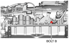
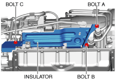
Insulator installation note
1. Temporarily tighten bolt B.
amxuuw00002860
|
2. Install the insulator and temporarily tighten bolts A and C in the order of A and C.
amxuuw00002861
|
3. Completely tighten bolts A, B, and C in the order of A, B, C.
TWC installation note
1. Remove the tunnel member temporarily.
amxuuw00003817
|
2. Install the TWC to the exhaust manifold (WU-TWC). (See EXHAUST SYSTEM REMOVAL/INSTALLATION [SKYACTIV-G 1.5, SKYACTIV-G 2.0].)
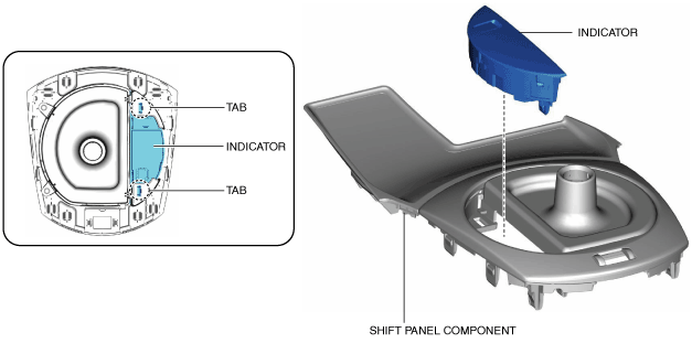
Indicator Removal/Installation
1. Disconnect the negative battery terminal. (See NEGATIVE BATTERY TERMINAL DISCONNECTION/CONNECTION.)
2. Remove the following parts:
3. Detach tabs shown in the figure and remove the indicator.
amxuuw00003584
|
4. Install in the reverse order of removal.