|
1
|
INSPECT FOR POWER SUPPLY-RELATED MALFUNCTION
• Switch the ignition ON (engine off).
• Perform the DTC inspection using the M-MDS.
• Is the power supply or DC-DC converter-related DTC displayed?
|
Yes
|
-
Note
-
• It may be affected by power supply-related or DC-DC converter malfunction.
Repair the malfunctioning location according to the applicable DTC troubleshooting.
|
|
No
|
Go to the next step.
|
|
2
|
INSPECT FOR SHORT TO POWER SUPPLY IN CAN_H SIDE CIRCUIT OF LOCAL-CAN
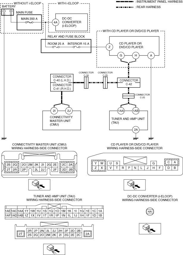
• Measure the voltage between connectivity master unit (CMU) terminal 2I (LOCAL-CAN CAN_H side) and body ground.
• Is the voltage B+?
|
Yes
|
A short to power supply in CAN_H side circuit of LOCAL-CAN has occurred.
• Go to Step 6.
|
|
No
|
Go to the next step.
|
|
3
|
INSPECT FOR SHORT TO GROUND IN CAN_L SIDE CIRCUIT OF LOCAL-CAN
• Measure the voltage between connectivity master unit (CMU) terminal 2J (LOCAL-CAN CAN_L side) and body ground.
• Is the voltage 0 V?
|
Yes
|
A short to ground in CAN_L side circuit of LOCAL-CAN has occurred.
• Go to Step 7.
|
|
No
|
Go to the next step.
|
|
4
|
INSPECT BETWEEN LOCAL-CAN_L AND LOCAL-CAN_H SIDE CIRCUITS FOR SHORT BETWEEN CIRCUITS
• Switch the ignition off.
• Disconnect the negative battery terminal.
• Measure the resistance between connectivity master unit (CMU) 2I and 2J terminals (wiring harness side).
• Is the resistance approx. 60 ohms?
|
Yes
|
Go to the next step. (LOCAL-CAN is normal)
|
|
No
|
If the resistance is 0 ohm:
• A short between circuits has occurred in LOCAL-CAN.
-
― Go to Step 8.
If the resistance is 120 ohms:
• An open circuit in the LOCAL-CAN has occurred.
-
― Go to Step 9.
|
|
5
|
DETERMINE MALFUNCTIONING LOCATION
• Connect the negative battery terminal.
• Clear the DTC for the connectivity master unit (CMU) using the M-MDS.
• Switch the ignition ON (engine off or on) and wait for 12 s or more.
• Retrieve the connectivity master unit (CMU) DTCs using the M-MDS.
• Is there any of the following DTCs being displayed?
-
― U0184:00
― U0187:00
|
Yes
|
If U0184:00 is only displayed:
• Go to Step 10.
If U0187:00 is only displayed:
• Go to Step 11.
If all DTCs are displayed:
• Replace the connectivity master unit (CMU), then go to Step 15.
|
|
No
|
Go to Step 16.
|
|
6
|
INSPECT WIRING HARNESS FOR SHORT TO POWER SUPPLY
• Switch the ignition off.
• Disconnect the negative battery terminal.
• Disconnect the following connectors:
-
― Connectivity master unit (CMU)
― Tuner and amp unit (TAU)
― CD player or DVD/CD player (With CD player or DVD/CD player)
• Connect the negative battery terminal.
• Switch the ignition ON (engine off or on).
• Measure the voltage at the following terminals (wiring harness side).
-
― Connectivity master unit (CMU) terminal 2I
― Tuner and amp unit (TAU) terminal 1AA
― CD player or DVD/CD player terminal G (With CD player or DVD/CD player)
• Is the voltage 0 V?
|
Yes
|
Go to Step 14.
|
|
No
|
Refer to the wiring diagram and verify if there is a common connector between the following terminals:
• Connectivity master unit (CMU) terminal 2I—Tuner and amp unit (TAU) terminal 1AA
• Connectivity master unit (CMU) terminal 2I—CD player or DVD/CD player terminal G (With CD player or DVD/CD player)
If there is a common connector:
• Determine the malfunctioning part by inspecting the common connector and the terminal for corrosion, damage, or pin disconnection, and the common wiring harness for a short to power supply.
• Repair or replace the malfunctioning part.
If there is no common connector:
• Repair or replace the wiring harness which has a short to power supply.
Go to Step 15.
|
|
7
|
INSPECT WIRING HARNESS FOR SHORT TO GROUND
• Switch the ignition off.
• Disconnect the negative battery terminal.
• Disconnect the following connectors:
-
― Connectivity master unit (CMU)
― Tuner and amp unit (TAU)
― CD player or DVD/CD player (With CD player or DVD/CD player)
• Inspect for continuity between the following terminals (wiring harness side) and body ground.
-
― Connectivity master unit (CMU) terminal 2J
― Tuner and amp unit (TAU) terminal 1AB
― CD player or DVD/CD player terminal H (With CD player or DVD/CD player)
• Is there continuity?
|
Yes
|
Refer to the wiring diagram and verify if there is a common connector between the following terminals:
• Connectivity master unit (CMU) terminal 2J—Tuner and amp unit (TAU) terminal 1AB
• Connectivity master unit (CMU) terminal 2J—CD player or DVD/CD player terminal H (With CD player or DVD/CD player)
If there is a common connector:
• Determine the malfunctioning part by inspecting the common connector and the terminal for corrosion, damage, or pin disconnection, and the common wiring harness for a short to ground.
• Repair or replace the malfunctioning part.
If there is no common connector:
• Repair or replace the wiring harness which has a short to ground.
Go to Step 15.
|
|
No
|
Go to Step 14.
|
|
8
|
INSPECT WIRING HARNESS FOR SHORT BETWEEN CIRCUITS
• Switch the ignition off.
• Disconnect the negative battery terminal.
• Disconnect the following connectors:
-
― Connectivity master unit (CMU)
― Tuner and amp unit (TAU)
― CD player or DVD/CD player (With CD player or DVD/CD player)
• Inspect between the following terminals (wiring harness side) for continuity.
-
― Connectivity master unit (CMU) terminals 2I and 2J
― Tuner and amp unit (TAU) terminals 1AA and 1AB
― CD player or DVD/CD player terminals G and H (With CD player or DVD/CD player)
• Is there continuity?
|
Yes
|
Refer to the wiring diagram and verify if there is a common connector between the following terminals:
• Connectivity master unit (CMU) terminal 2I—Tuner and amp unit (TAU) terminal 1AA
• Connectivity master unit (CMU) terminal 2J—Tuner and amp unit (TAU) terminal 1AB
• Connectivity master unit (CMU) terminal 2I—CD player or DVD/CD player terminal G (With CD player or DVD/CD player)
• Connectivity master unit (CMU) terminal 2J—CD player or DVD/CD player terminal H (With CD player or DVD/CD player)
If there is a common connector:
• Inspect the common connector and terminals for corrosion, damage, or disconnection and the common wiring harnesses for short between circuits to determine the malfunctioning location.
• Repair or replace the malfunctioning part.
If there is no common connector:
• Repair or replace the wiring harness which has shorted between circuits.
Go to Step 15.
|
|
No
|
Go to Step 14.
|
|
9
|
INSPECT WIRING HARNESS FOR OPEN CIRCUIT
• Switch the ignition off.
• Disconnect the negative battery terminal.
• Disconnect the following connectors:
-
― Connectivity master unit (CMU)
― Tuner and amp unit (TAU)
― CD player or DVD/CD player (With CD player or DVD/CD player)
• Inspect the wiring harness for continuity between the following terminals (wiring harness side).
-
• Connectivity master unit (CMU) terminal 2I—Tuner and amp unit (TAU) terminal 1AA
• Connectivity master unit (CMU) terminal 2J—Tuner and amp unit (TAU) terminal 1AB
• Connectivity master unit (CMU) terminal 2I—CD player or DVD/CD player terminal G (With CD player or DVD/CD player)
• Connectivity master unit (CMU) terminal 2J—CD player or DVD/CD player terminal H (With CD player or DVD/CD player)
• Is there continuity?
|
Yes
|
Go to Step 14.
|
|
No
|
Refer to the wiring diagram and verify if there is a common connector between the following terminals:
• Connectivity master unit (CMU) terminal 2I—Tuner and amp unit (TAU) terminal 1AA
• Connectivity master unit (CMU) terminal 2J—Tuner and amp unit (TAU) terminal 1AB
• Connectivity master unit (CMU) terminal 2I—CD player or DVD/CD player terminal G (With CD player or DVD/CD player)
• Connectivity master unit (CMU) terminal 2J—CD player or DVD/CD player terminal H (With CD player or DVD/CD player)
If there is a common connector:
• Determine the malfunctioning part by inspecting the common connector and the terminal for corrosion, damage, or pin disconnection, and the common wiring harness for an open circuit.
• Repair or replace the malfunctioning part.
If there is no common connector:
• Repair or replace the wiring harness which has an open circuit.
Go to Step 15.
|
|
10
|
INSPECT TUNER AND AMP UNIT (TAU) RELATED-WIRING HARNESS FOR OPEN CIRCUIT
• Switch the ignition off.
• Disconnect the negative battery terminal.
• Disconnect the tuner and amp unit (TAU) connector.
• Inspect the wiring harness for continuity between tuner and amp unit (TAU) terminal 2A and ground.
• Is there continuity?
|
Yes
|
Replace the tuner and amp unit (TAU), then go to Step 15.
|
|
No
|
Refer to the wiring diagram and verify if there is a common connector between tuner and amp unit (TAU) terminal 2A and ground.
If there is a common connector:
• Determine the malfunctioning part by inspecting the common connector and the terminal for corrosion, damage, or pin disconnection, and the common wiring harness for an open circuit.
• Repair or replace the malfunctioning part.
If there is no common connector:
• Repair or replace the wiring harness which has an open circuit.
Go to Step 15.
|
|
11
|
INSPECT CD PLAYER OR DVD/CD PLAYER RELATED-WIRING HARNESS FOR OPEN CIRCUIT
• Switch the ignition off.
• Disconnect the negative battery terminal.
• Disconnect the CD player or DVD/CD player connector.
• Inspect the wiring harness for continuity between CD player or DVD/CD player terminal A (wiring harness side) and ground.
• Is there continuity?
|
Yes
|
Without i-ELOOP:
• Go to the next step.
With i-ELOOP:
• Go to Step 13.
|
|
No
|
Refer to the wiring diagram and verify if there is a common connector between CD player or DVD/CD player terminal A and ground.
If there is a common connector:
• Determine the malfunctioning part by inspecting the common connector and the terminal for corrosion, damage, or pin disconnection, and the common wiring harness for an open circuit.
• Repair or replace the malfunctioning part.
If there is no common connector:
• Repair or replace the wiring harness which has an open circuit.
Go to Step 15.
|
|
12
|
VERIFY CD PLAYER OR DVD/CD PLAYER POWER SUPPLY VOLTAGE
• Verify that the CD player or DVD/CD player connector is disconnected.
• Connect the negative battery terminal.
• Switch the ignition ON (engine off or on).
• Measure the voltage at CD player or DVD/CD player terminal Z (wiring harness side).
• Is the voltage B+?
|
Yes
|
Replace the CD player or DVD/CD player, then go to Step 15.
|
|
No
|
Inspect the INTERIOR 15 A fuse, ROOM 25 A fuse and MAIN 200 A fuse.
• Any fuse is blown:
-
― Refer to the wiring diagram and verify if there is a common connector between MAIN 200 A fuse and CD player or DVD/CD player terminal Z.
If there is a common connector:
-
• Determine the malfunctioning part by inspecting the common connector and the terminal for corrosion, damage, or pin disconnection, and the common wiring harness for a short to ground.
• Repair or replace the malfunctioning part.
If there is no common connector:
-
• Repair or replace the wiring harness which has a short to ground.
• Replace the fuse.
• Any fuse is damaged:
-
― Replace the fuse.
• All fuses are normal:
-
― Refer to the wiring diagram and verify if there is a common connector between battery positive terminal and CD player or DVD/CD player terminal Z.
If there is a common connector:
-
• Determine the malfunctioning part by inspecting the common connector and the terminal for corrosion, damage, or pin disconnection, and the common wiring harness for an open circuit.
• Repair or replace the malfunctioning part.
If there is no common connector:
-
• Repair or replace the wiring harness which has an open circuit.
Go to Step 15.
|
|
13
|
VERIFY CD PLAYER OR DVD/CD PLAYER POWER SUPPLY VOLTAGE
• Verify that the CD player or DVD/CD player connector is disconnected.
• Connect the negative battery terminal.
• Switch the ignition ON (engine off or on).
• Measure the voltage at CD player or DVD/CD player terminal Z (wiring harness side).
• Is the voltage B+?
|
Yes
|
Replace the CD player or DVD/CD player, then go to Step 15.
|
|
No
|
Disconnect the service plug.
Inspect the INTERIOR 15 A fuse and ROOM 25 A fuse.
• Any fuse is blown:
-
― Refer to the wiring diagram and verify if there is a common connector between ROOM 25 A fuse and CD player or DVD/CD player terminal Z.
If there is a common connector:
-
• Determine the malfunctioning location by inspecting the common connector and terminals for corrosion, damage, or disconnection and by inspecting the DC-DC converter (i-ELOOP) terminal 4A-related wiring harness for a short to ground.
• Repair or replace the malfunctioning part.
If there is no common connector:
-
• Repair or replace the wiring harness which has a short to ground.
• Replace the fuse.
• Any fuse is damaged:
-
― Replace the fuse.
• All fuses are normal:
-
― Refer to the wiring diagram and verify if there is a common connector between DC-DC converter (i-ELOOP) terminal 4A and CD player or DVD/CD player terminal Z.
If there is a common connector:
-
• Determine the malfunctioning part by inspecting the common connector and the terminal for corrosion, damage, or pin disconnection, and the common wiring harness for an open circuit.
• Repair or replace the malfunctioning part.
If there is no common connector:
-
• Repair or replace the wiring harness which has an open circuit.
Go to Step 15.
|
|
14
|
PERFORM DTC INSPECTION AND DETERMINE MALFUNCTIONING LOCATION
• Always reconnect all disconnected connectors.
• Connect the negative battery terminal.
• Clear the DTC for the connectivity master unit (CMU) using the M-MDS.
• Switch the ignition ON (engine off or on) and wait for 12 s or more.
• Retrieve the connectivity master unit (CMU) DTCs using the M-MDS.
• Is there any of the following DTCs being displayed?
-
― U0184:00
― U0187:00
|
Yes
|
If U0184:00 is only displayed:
• Replace the tuner and amp unit (TAU), then go to the next step.
If U0187:00 is only displayed:
• Replace the CD player or DVD/CD player, then go to the next step.
If all DTCs are displayed:
• Replace the connectivity master unit (CMU), then go to the next step.
|
|
No
|
Go to Step 16.
|
|
15
|
VERIFY THAT REPAIRS HAVE BEEN COMPLETED
• Always reconnect all disconnected connectors.
• Connect the negative battery terminal.
• Clear the DTC for the connectivity master unit (CMU) using the M-MDS.
• Switch the ignition ON (engine off or on) and wait for 12 s or more.
• Retrieve the connectivity master unit (CMU) DTCs using the M-MDS.
• Is the same Pending DTC present?
|
Yes
|
Repeat the inspection from Step 1.
• If the malfunction recurs, replace the connectivity master unit (CMU).
Go to the next step.
|
|
No
|
Go to the next step.
|
|
16
|
VERIFY IF OTHER DTCs DISPLAYED
• Are any other DTCs displayed?
|
Yes
|
Repair or replace the malfunctioning part according to the applicable DTC troubleshooting.
|
|
No
|
DTC troubleshooting completed.
|