 |
amxuuw00002894
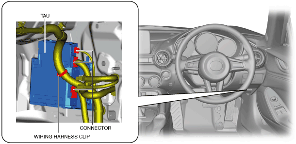
TUNER AND AMP UNIT (TAU) REMOVAL/INSTALLATION
id092000031200
L.H.D.
1. Disconnect the negative battery terminal. (See NEGATIVE BATTERY TERMINAL DISCONNECTION/CONNECTION.)
2. Remove the following parts:
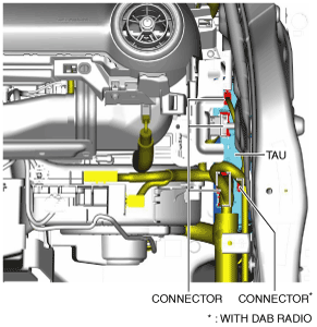
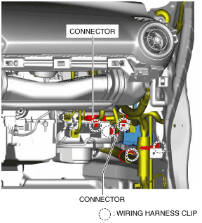
3. Disconnect the connectors.
amxuuw00002894
|
4. Pull out the wiring harness clips.
5. Disconnect the connectors.
amxzzw00003567
|
6. Remove the bolts.
amxzzw00003570
|
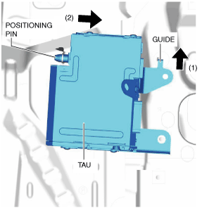
7. Move the TAU in the direction of arrow (1) shown in the figure and detach the guide from the body.
amxzzw00003571
|
8. Move the TAU in the direction of arrow (2) shown in the figure and detach the positioning pin from the body.
9. Move the TAU to the position shown in the figure.
amxzzw00003568
|
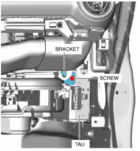
10. Remove the screw, then remove the bracket.
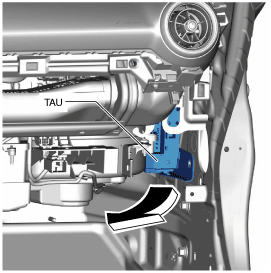
11. Remove the TAU in the direction of the arrow shown in the figure.
amxuuw00002898
|
12. Install in the reverse order of removal.
R.H.D.
1. Disconnect the negative battery terminal. (See NEGATIVE BATTERY TERMINAL DISCONNECTION/CONNECTION.)
2. Remove the scuff plate. (driver's side) (See SCUFF PLATE REMOVAL/INSTALLATION.)
3. Remove the front side trim. (driver's side) (See FRONT SIDE TRIM REMOVAL/INSTALLATION.)
4. Remove the bonnet release lever. (See BONNET RELEASE LEVER AND RELEASE CABLE REMOVAL/INSTALLATION.)
5. Pull out the wiring harness clip.
amxzzw00003569
|
6. Disconnect the connectors.
7. Remove the bolts.
amxzzw00003570
|
8. Move the TAU in the direction of arrow (1) shown in the figure and detach the guide from the body.
amxzzw00003571
|
9. Move the TAU in the direction of arrow (2) shown in the figure, detach the positioning pin from the body, and remove the TAU.
10. Install in the reverse order of removal.