|
1
|
VERIFY PCM DTCs
• Retrieve the PCM DTCs using the M-MDS.
• Are any DTCs displayed?
|
Yes
|
Repair or replace the malfunctioning part according to the applicable DTC troubleshooting.
|
|
No
|
Without i-ELOOP:
• Go to Step 3.
With i-ELOOP:
• Go to the next step.
|
|
2
|
VERIFY DC-DC CONVERTER (i-ELOOP) DTCs
• Retrieve the DC-DC converter (i-ELOOP) DTCs using the M-MDS.
• Are any DTCs displayed?
|
Yes
|
Repair or replace the malfunctioning part according to the applicable DTC troubleshooting.
|
|
No
|
Go to the next step.
|
|
3
|
INSPECT BATTERY
• Is the battery normal?
|
Yes
|
Go to the next step.
|
|
No
|
Recharge or replace the battery, then go to Step 8.
|
|
4
|
INSPECT GENERATOR
• Is the generator normal?
|
Yes
|
Go to the next step.
|
|
No
|
Replace the generator, then go to Step 8.
|
|
5
|
INSPECT START STOP UNIT CONNECTOR CONDITION
• Switch the ignition off.
• Disconnect the negative battery terminal.
• Disconnect the start stop unit connector.
• Inspect the connector engagement and connection condition and inspect the terminals for damage, deformation, corrosion, or disconnection.
• Is the connector normal?
|
Yes
|
Without i-ELOOP:
• Go to the next step.
With i-ELOOP:
• Go to Step 7.
|
|
No
|
Repair or replace the connector, then go to Step 8.
|
|
6
|
VERIFY START STOP UNIT POWER SUPPLY VOLTAGE (TERMINAL 1A)
• Always reconnect all disconnected connectors.
• Connect the negative battery terminal.
• Display PID VPWR_B1 using the M-MDS.
• Is the voltage 5 V or more or less than 8.5 V?
|
Yes
|
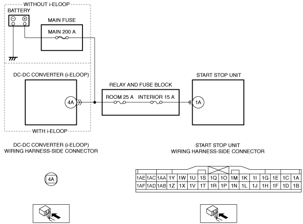
Refer to the wiring diagram and verify whether or not there is a common connector between battery positive terminal and start stop unit terminal 1A.
If there is a common connector:
• Determine the malfunctioning part by inspecting the common connector and the terminal for corrosion, damage, or pin disconnection, and the common wiring harness for a malfunction.
• Repair or replace the malfunctioning part.
If there is no common connector:
• Inspect the wiring harness battery positive terminal and start stop unit terminal 1A.
-
― If there is any malfunction:
-
• Repair or replace the wiring harness.
― If there is no malfunction:
-
• Replace the start stop unit.
Go to Step 8.
|
|
No
|
Go to Step 8.
|
|
7
|
VERIFY START STOP UNIT POWER SUPPLY VOLTAGE (TERMINAL 1A)
• Always reconnect all disconnected connectors.
• Connect the negative battery terminal.
• Display PID VPWR_B1 using the M-MDS.
• Is the voltage 5 V or more or less than 8.5 V?
|
Yes
|
Disconnect the service plug.
Refer to the wiring diagram and verify whether or not there is a common connector between DC-DC converter (i-ELOOP) terminal 4A and start stop unit terminal 1A.
If there is a common connector:
• Determine the malfunctioning part by inspecting the common connector and the terminal for corrosion, damage, or pin disconnection, and the common wiring harness for a malfunction.
• Repair or replace the malfunctioning part.
If there is no common connector:
• Inspect the wiring harness DC-DC converter (i-ELOOP) terminal 4A and start stop unit terminal 1A.
-
― If there is any malfunction:
-
• Repair or replace the wiring harness.
― If there is no malfunction:
-
• Replace the start stop unit.
Connect the service plug, then go to the next step.
|
|
No
|
Go to the next step.
|
|
8
|
VERIFY THAT REPAIRS HAVE BEEN COMPLETED
• Always reconnect all disconnected connectors.
• Connect the negative battery terminal.
• Clear the DTC for the start stop unit using the M-MDS.
• Switch the ignition ON (engine off or on) and wait for 5 s or more.
• Retrieve the start stop unit DTCs using the M-MDS.
• Is the same Pending DTC present?
|
Yes
|
Repeat the inspection from Step 1.
• If the malfunction recurs, replace the start stop unit.
Go to the next step.
|
|
No
|
Go to the next step.
|
|
9
|
VERIFY IF OTHER DTCs DISPLAYED
• Are any other DTCs displayed?
|
Yes
|
Repair or replace the malfunctioning part according to the applicable DTC troubleshooting.
|
|
No
|
DTC troubleshooting completed.
|