|
1
|
VERIFY OTHER RETRACTABLE HARDTOP CONTROL MODULE DTCs
• Clear the DTC for the retractable hardtop control module using the M-MDS.
• Retrieve the retractable hardtop control module DTCs using the M-MDS.
• Is the DTCs U3000:44/U3000:45/U3000:49 displayed?
|
Yes
|
Replace the retractable hardtop control module, then go to Step 7.
|
|
No
|
Go to the next step.
|
|
2
|
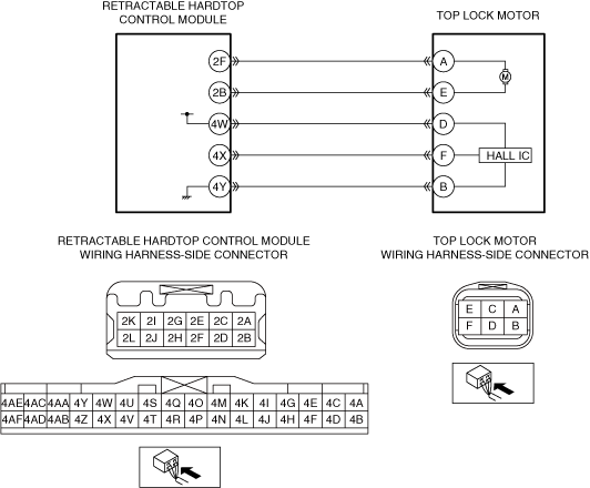
INSPECT TOP LOCK MOTOR CIRCUIT FOR SHORT TO GROUND
• Switch the ignition off.
• Disconnect the negative battery terminal.
• Disconnect the retractable hardtop control module and top lock motor connectors.
• Inspect for continuity between the following terminals (wiring harness-side) and body ground:
-
― Top lock motor terminal F
― Top lock motor terminal D
• Is there continuity?
|
Yes
|
Refer to the wiring diagram and verify whether or not there is a common connector between the following terminals:
• Retractable hardtop control module terminal 4X and top lock motor terminal F
• Retractable hardtop control module terminal 4W and top lock motor terminal D
If there is a common connector:
• Determine the malfunctioning part by inspecting the common connector and the terminal for corrosion, damage, or pin disconnection, and the common wiring harness for a short to ground.
• Repair or replace the malfunctioning part.
If there is no common connector:
• Repair or replace the wiring harness which has a short to ground.
Go to Step 7.
|
|
No
|
Go to the next step.
|
|
3
|
INSPECT TOP LOCK MOTOR CIRCUIT FOR SHORT TO POWER SUPPLY
• Verify that the retractable hardtop control module and top lock motor connectors are disconnected.
• Connect the negative battery terminal.
• Switch the ignition ON (engine off or on).
• Measure the voltage at the following terminals (wiring harness-side):
-
― Top lock motor terminal F
― Top lock motor terminal B
• Is the voltage 0 V?
|
Yes
|
Go to the next step.
|
|
No
|
Refer to the wiring diagram and verify whether or not there is a common connector between the following terminals:
• Retractable hardtop control module terminal 4X and top lock motor terminal F
• Retractable hardtop control module terminal 4Y and top lock motor terminal B
If there is a common connector:
• Determine the malfunctioning part by inspecting the common connector and the terminal for corrosion, damage, or pin disconnection, and the common wiring harness for a short to power supply.
• Repair or replace the malfunctioning part.
If there is no common connector:
• Repair or replace the wiring harness which has a short to power supply.
Go to Step 7.
|
|
4
|
INSPECT TOP LOCK MOTOR CIRCUIT FOR OPEN CIRCUIT
• Switch the ignition off.
• Disconnect the negative battery terminal.
• Verify that the retractable hardtop control module and top lock motor connectors are disconnected.
• Inspect the wiring harness for continuity between the following terminals (wiring harness-side):
-
― Retractable hardtop control module terminal 4X and top lock motor terminal F
― Retractable hardtop control module terminal 4Y and top lock motor terminal B
― Retractable hardtop control module terminal 4W and top lock motor terminal D
• Is there continuity?
|
Yes
|
Refer to the wiring diagram and verify whether or not there is a common connector between the following terminals:
• Retractable hardtop control module terminal 4X and top lock motor terminal F
• Retractable hardtop control module terminal 4Y and top lock motor terminal B
• Retractable hardtop control module terminal 4W and top lock motor terminal D
If there is a common connector:
• Determine the malfunctioning part by inspecting the common connector and the terminal for corrosion, damage, or pin disconnection, and the common wiring harness for an open circuit.
• Repair or replace the malfunctioning part.
If there is no common connector:
• Repair or replace the wiring harness which has an open circuit.
Go to Step 7.
|
|
No
|
Go to the next step.
|
|
5
|
INSPECT TOP LOCK MOTOR CIRCUIT FOR SHORT BETWEEN CIRCUITS
• Verify that the retractable hardtop control module and top lock motor connectors are disconnected.
• Inspect for continuity between the following terminals (wiring harness-side):
-
― Top lock motor terminal F and top lock motor terminal D
― Top lock motor terminal F and top lock motor terminal B
― Top lock motor terminal D and top lock motor terminal B
• Is there continuity?
|
Yes
|
Go to the next step.
|
|
No
|
Refer to the wiring diagram and verify whether or not there is a common connector between the following terminals:
• Top lock motor terminal F and top lock motor terminal D
• Top lock motor terminal F and top lock motor terminal B
• Top lock motor terminal D and top lock motor terminal B
If there is a common connector:
• Determine the malfunctioning part by inspecting the common connector and the terminal for corrosion, damage, or pin disconnection, and the common wiring harness for a short between circuit.
• Repair or replace the malfunctioning part.
If there is no common connector:
• Repair or replace the wiring harness which has a short between circuit.
Go to Step 7.
|
|
6
|
INSPECT TOP LOCK MOTOR
• Inspect the top lock motor.
• Is the top lock motor normal?
|
Yes
|
Go to the next step.
|
|
No
|
Replace the top lock motor, then go to the next step.
|
|
7
|
VERIFY THAT REPAIRS HAVE BEEN COMPLETED
• Always reconnect all disconnected connectors.
• Connect the negative battery terminal.
• Clear the DTC for the retractable hardtop control module using the M-MDS.
• Retrieve the retractable hardtop control module DTCs using the M-MDS.
• Is the same Pending DTC present?
|
Yes
|
Repeat the inspection from Step 1.
• If the malfunction recurs, replace the retractable hardtop control module.
Go to the next step.
|
|
No
|
Go to the next step.
|
|
8
|
VERIFY IF OTHER DTCs DISPLAYED
• Are any other DTCs displayed?
|
Yes
|
Repair or replace the malfunctioning part according to the applicable DTC troubleshooting.
|
|
No
|
DTC troubleshooting completed.
|